Advanced Tutorial on Wireless Communication and Electronic Tracking: CT System Survivability, Reliability, And Availability
4.1 General Considerations
Ideally, mines should install CT systems that can survive and remain operational, or can be quickly made operational, following an emergency event to meet the requirements of the MINER Act of 2006. Examples of major emergency events are methane and coal dust explosions, fires, roof falls, and water inundations. The key requirement is to improve emergency response in the event of a crisis by having the communications system survive, or at least be quickly reconfigurable or repairable, so that there can be communications between miners and surface personnel. Failure of the system could be either a result of the emergency event or a random failure of a critical component of the system.
Frequently following a significant emergency event in the mine, the power is shut down to prevent possible sparking or heating that might initiate a fire or explosion due to a possible buildup of flammable gases after the incident. Therefore, if CT systems are to remain operational, they will need to have a permissible backup power source.
In discussing the quality of a system, as opposed to its technical performance, the terms survivability, reliability, and availability are frequently used. In this tutorial, they are used in the context of systems engineering, i.e., the engineering discipline that considers complex systems in an organized, systematic manner. Each of these terms is discussed below.
Survivability is the ability of a system to provide essential services in spite of an accident. The definition does not require that the system perform exactly as it did before an accident, but that it does provide essential services after an accident.
Reliability can be defined in several ways depending on the objectives of the CT system. Reliability is frequently represented as a probability or as a percentage. Examples of reliability objectives include:
- The ability of a system to perform its specified functions.
- The ability of a system to perform without failures.
- The ability of a system to perform without repairs or maintenance.
Reliability has two aspects. Basic reliability refers to the ability of a system to operate without repairs or adjustments. Operational reliability refers to the ability of a system to perform and complete its functions satisfactorily.
Availability is the proportion of time a system is in a functioning state and able to provide its services. Availability also takes into account the time needed to repair a system, because while undergoing repair the system is assumed to be unavailable.
Survivability, reliability, and availability are measures of the quality of a system. They assess different but interrelated qualities that measure the ability of a system to meet performance requirements. For example, redundant communications paths have been introduced as a technique to increase the survivability of a communications system. Adding a redundant path means adding components and complexity to a system which would increase the operational reliability, but may cause the basic reliability to decrease because of the increase in the number of components that could potentially fail. The availability could increase, decrease, or stay the same, depending on the impact on the time to repair and time between repairs.
Survivability and reliability will be discussed in Section 4.2. Availability is discussed in more detail in Section 4.3.
4.1.1 Objectives and Approaches
In consumer products, there may not be any specific requirements regarding survivability, reliability, and availability. Nevertheless, market forces will frequently drive the manufacturers to improve these qualities. For example, people will not intentionally purchase a car known to be unreliable. Or a consumer may be interested in purchasing a car known to have more safety features, making it more likely for a driver to survive an accident. Products that are considered life-critical, where the failure of the system may cause death or serious injury to people, will generally have specific quantitative requirements on survivability, reliability, and availability.
In the underground coal mining industry, the importance of CT systems has long been recognized. In particular, their importance in being operational following an emergency event has been recognized and is being mandated by MSHA. CT technologies used in surface applications are being adapted to the mine environment, and new technologies are being developed. Methods to enhance survivability are being proposed and evaluated, such as combining different technologies, installing alternate communications paths, providing protection or hardening of components, and developing permissible batteries to serve as backup power supplies.
These topics are covered in more detail below. Section 4.2 begins with a discussion of anticipated emergency events, how CT systems might fail based on these events, how CT systems can be improved to potentially overcome failures from these events, and finally, how CT systems can be modeled to assess the benefits of various system options.
4.2 Survivability and Reliability
Examples of major emergency conditions likely to be encountered by CT systems in an underground coal mine fall into four overall categories:
- Explosions. Includes methane-only explosions and coal dust explosions typically caused by suspended or disturbed coal dust following an initial methane explosion.
- Fires. Includes the ignition of various types of fires, their progress and intensification, and likely distribution within and through mine passages. These fires can comprise those following mine explosions, those due to faulty equipment, and those initiated through inadvertent human action.
- Roof falls, pillar bursts, and related ground control accidents. Includes situations involving falls or expulsion of significant amounts of debris from mine passage surfaces, such as roofs, pillars, ribs, and other excavated underground areas.
- Inundations. Includes sudden water inundation with potentially high water depths and long-term, chronically wet mine passage conditions.
The associated environmental conditions produced from these emergency conditions can include high temperatures, high-pressure waves and air velocities, collisions with rapidly moving or heavy objects, stress or load concentrations, and water damage. Cables and connectors, electrical and electronic components, batteries, antennas, and external power supplies or battery-charging systems are all susceptible to damage.
Based on studies sponsored by NIOSH [QinetiQ 2008], it was found that the majority of recent major coal mine accidents (1990-2008) were methane and coal dust explosions. Such explosions have resulted in the most significant instances of damage to CT systems and are being used as the basis for recommendation for hardening and redundancy improvements.
In most of the studied cases, at least some if not most of the underground miners were in their working sections when an accident occurred, though they were not always the victims of the events. In numerous cases, accidents were triggered in outby or remote areas, and the victims at those locations were often killed instantly.
It should be noted that in none of the cases studied to date did communications or monitoring systems cause the initial ignition or explosion. Rarely were there secondary explosions and even when they did occur, there was no data found to indicate that the additional explosions were caused by these systems. It is fair to assume that the likelihood of these systems causing ignitions or explosions is small.
The study [QinetiQ 2008] concludes that the forces likely to be encountered during coal mine accidents include:
- Explosions where peak blast pressures range from approximately 3.1 bars (45 psi) down to 0.6 bars (8 psi) depending on the distance from the blast and whether the exposure is direct (i.e., line-of-sight) or indirect (i.e., not line-of-sight). Peaks from methane-only explosions are typically on the order of 1/3 second in duration. With coal dust involved, these peaks will last longer. The resultant explosive forces leave very little equipment intact in the path of the explosion.
- Fires, when fully developed, can range up to 1,100°C-1,400°C (2,000°F-2,500°F). In addition, roof temperatures above localized fires (e.g., fires on or around a piece of mining equipment or a conveyor belt can range up to 200°C-550°C (400°F-1,000°F).
- Roof falls, pillar bursts and related ground control accidents can leave a mass of debris. Each 300 cubic meters (1,000 cubic feet) of rock debris can weigh as much as 36-72 metric tons (40-80 tons). Depending upon the size and shape of the fallen debris, a floor load impact could be 0.7-1.4 bars (10-20 psi). In fact, if the debris load is concentrated the impact can be as great as 17-35 bars (250-500 psi).
- Water inundations, assuming a water depth of 60 m (200 ft), can result in a 7-bars (100-psi) pressure for up to 200 hours.
![Figure 4-1. Example of a miner activity/travel and roof-fall probability map [Iannacchione et. al. 2007].](../../../UserFiles/content/emergencymanagementandresponse/commtracking/commtrackingtutorial2/4-1.png)
[Iannacchione et. al. 2007].
To address some of these issues, the QinetiQ [2008] study notes that it may be possible to mount pagers and other smaller equipment in the rib. It is also possible to locally protect cables in crosscuts by fixing protective plates over the cables and into the roof. The probability of roof falls for specific areas of the mine should be determined using a roof-fall rating index (RFRI) along with a probability map showing the areas where the miners are working and traveling throughout the mine as shown in the example in Figure 4-1 [Iannacchione et al. 2007].
4.2.1 Survivability of CT Systems
It should be noted that it is highly impractical, if not impossible, to design a CT system such that the entire system could survive any and every imaginable emergency event. There will always be an event that is too large, too energetic, or too devastating for the parts of the CT system in the immediate vicinity of the event to survive. The goal of the system design should be to ensure that the parts of the CT system that are not in the direct vicinity of the event remain operational. Given the linear nature of coal mines, systems that can use alternate communications paths out of the mine can help ensure this type of survivability. The objective of this discussion is to provide a knowledge base and tools that can be used to consider tradeoffs to determine the best CT approach for the constraints of a given mine.
As discussed above, survivability is defined as a system’s (component, cable, antenna) ability to continue to provide services considered essential and operations-critical in spite of either accidental or malicious harm to the system. For underground coal mining CT systems, survivability may be considered the ability of the system to provide communications coverage in critical areas of the mine after an emergency event, such as an explosion, fire, roof fall, or water inundation.
The key questions a mine operator must be concerned with when considering system survivability are:
- With respect to the origination point of the event, which parts or components of the system are most likely to survive and continue to function post-event?
- Assuming that some components will be damaged and nonfunctional, how will the loss of those components affect the coverage of the system?
- Post-event, will the system still provide coverage to critical areas of the mine?
- How may system coverage in critical areas be better protected and preserved post-event?
A survivability assessment will also take into account the configuration of the system, including the proximity of those components to potential origination points of an explosion, fire, roof fall, or water inundation.
The survivability of the system depends upon which components are still functional and which are not functional after the emergency event. In the mining environment, the survivability of the individual components will depend upon the locations of the components with respect to the origin of the event. For example, components located directly next to an explosion site will probably not survive. Moreover, components not directly next to the explosion site, but that are in line with the direction of travel of the blast pressure wave may or may not survive, depending upon the proximal distance, how that component is installed, and whether the component has been hardened or otherwise protected. However, components that are at a very great distance from the explosion site will most likely survive, especially if they are not located directly in the line of the pressure wave.
The ability of a component to survive an event will increase if the appropriate protection has been implemented, i.e., the extent to which the component is protected from adverse harm will help determine whether or not that component is likely to survive. Also, components that are at higher risk for being damaged will benefit from additional protection. For example, a coal mine operator may consider implementing additional protections for components located close to the working face, where risks for explosions are greater than in a travel way. The metric that is most useful for determining survivability of a communications, tracking, or atmospheric monitoring system (AMS) is system coverage. Therefore, a coal mine operator should take into consideration how much coverage would be potentially lost if the more vulnerable components of the specific system were to become nonfunctional. The result of this analysis may determine the system configuration and component placement in the mine.
The ability of a component to survive an event is based upon several factors, including the following:
- Amount of hardening of the cable or component.
- Whether the component is in a fireproof/crushproof box.
- Mounting techniques used on the cable or component.
- Orientation of the cable or component with respect to the expected line of force from a blast.
- Whether the cable or component is buried.
- Whether the cable or component is protected with sandbags.
- Whether the cable or component is recessed into the rib.
In addition to improving survivability of system components, there are also other methods to improve survivability of system coverage. For example, a mine operator should try to place more critical components of the CT system away from areas that are at higher risk of experiencing an event. By doing this, the critical components will be more likely to survive an emergency event and preserve overall system coverage. Also, having redundant communications in less vulnerable areas of the mine (for example, in an adjacent entry) may preserve paths of communications.
4.2.2 Reliability of CT Systems
As an engineering discipline, reliability is known as an area of study aimed at determining, evaluating, and modeling the ability of a system to perform its function or functions under specified conditions and parameters. In standard applications, reliability is expressed as a probability that the system will perform its expected functions within certain operating environments and times.
However, for underground coal mining CT systems, the mine operator has additional considerations besides the ability of the system to function as specified by the manufacturer. The mine operator needs to know the likelihood that a system will function in critical areas of the mine, e.g., the working face, or the travel ways. If the system experiences any failures, the mine operator needs assurance that those failures will have minimal impact on communications coverage in critical areas. This issue is best summarized as a communications coverage assessment. Therefore, the mine operator is most interested in knowing the following:
- What areas in the mine have communications coverage?
- How reliably will the system provide communications coverage to those areas?
- Due to the configuration of the system or reliability of the components, how reliably will the system provide communications coverage in critical areas of the mine?
A communications coverage assessment will take into account the reliability of each section of the system. Reliability of each section is determined by the mean time between failures (MTBF) data of the section’s components and the component configuration. A mine operator should obtain this data from the system’s manufacturer.
The communications coverage responsibility of each section is determined by the components and configuration within that section. In some CT systems, losing functionality of an outby section of the system means that all sections inby that lost section also cease functioning. Therefore, during an assessment, the more coverage for which the section is responsible, the more critical that section is to the overall ability of the system to provide coverage.
Some areas of the mine are critical for communications, and the ability of the system to provide reliable post-accident communications coverage in those areas is paramount. In certain areas of the mine, such as the working face, having coverage is much more critical than in seldom-used areas of the mine. A communications coverage assessment of the mine would include determining where these critical areas are located and configuring the system to have highly reliable coverage performance in those areas.
The reliability of the CT system is determined by:
- Reliability of each of the system’s components (electronics, battery, antenna).
- Reliability of each component’s interconnections (cables, connectors).
- Configuration of the components, especially when considering series (in-line) or parallel (redundant) configurations.
Reliability of the system and its components is measured in terms of MTBF data, which assess the ability of the system to perform without failure, within specified times, and under specified conditions. MTBF is expressed in units of time and should be available from the system’s manufacturer.
The system’s manufacturer determines MTBF in several different ways, including testing, analysis of historical data, theoretical modeling or simulation, and comparison to similar systems or components. Whatever the means of collecting the data, the methods used by the manufacturer should result in data representative of the system’s ability to perform its desired function (i.e., voice communications, tracking information, data transfer, atmospheric monitoring) in the operating environments and conditions expected in actual use. Therefore, MTBF data collected from testing the component on a bench in a lab might not be necessarily representative of the component’s performance in the mine, which, in some cases, may be a much more caustic, humid, or hot environment.
For systems lacking sufficient historical data or comparisons against which to evaluate, testing is a popular method by which manufacturers determine reliability. Reliability tests are commonly divided into various categories, including environmental (i.e., coal and rock dust, humidity, resistance to chemicals, salt spray), mechanical (i.e., vibration, mechanical shock, pressure), and electrical (i.e., overvoltage, reserve voltage, electric static discharge).
To a certain point, the reliability of the CT system and its components is limited by the system’s design. However, through path redundancy, coverage redundancy, and careful consideration of the system configuration, mine operators can improve the ability of the system to reliably cover critical areas.
Path redundancy of components or sections of the system allows for alternate success paths for communications. For single-path systems, one break in that path will render the rest of the system inoperable. However, when redundant paths exist, communications signals can travel along an alternate parallel path to reach their intended endpoint even though the main path may be cut. Coverage redundancy refers to overlapping coverage sections, so that if one component or portion of a system becomes nonfunctional, that area will still be covered by another component or portion of the system. Lastly, the system configuration may help to increase reliability. Certain areas of the mine may be more active, and equipment may be more likely to be damaged in those highly active areas when compared to less active areas of the mine. It would therefore be wise to place critical sections of a system away from these highly active areas.
A pre-event coverage reliability assessment allows the mining operator to determine overall, day-to-day system coverage based upon the reliability of each section. Due to the probabilistic nature of MTBF, the pre-event reliability assessment determines the likelihood that the system will provide the required coverage over a given amount of time.
4.2.3 Techniques to Enhance Survivability and Reliability
There are several approaches to consider when increasing the survivability and/or reliability of a CT system. Three different techniques are discussed in this section: hardening, redundancy, and reconfiguration.
4.2.3.1 Hardening Techniques
Hardening is a term used to describe the techniques that are used to protect equipment from explosive forces, inadvertent collisions, rock falls, and possibly fires. Hardening reduces the potential for damage to the CT system, which thereby increases its survivability. However, hardening may increase the time required to repair such parts, which would decrease the basic reliability.
Cables and Connectors
Use of reinforced cables, conduit, supplementary cable shielding, and in-floor trenching for cabling are techniques to help protect the cable from pressure waves and flying debris. Encasement, shielding, or recessing of component enclosures may also help minimize damage from explosive blast forces and flying debris.
The cabling and electrical components of typical CT systems are normally strung through mine entries without special provisions for physical protection, other than mounting them as high as reasonably possible to reduce snagging by personnel, vehicles, or other equipment. While the cabling, wiring, or electrical boxes have some modest degree of strength, the combination of being the usual industrial configuration, plus a "hanging" style of installation, make them quite vulnerable to blast and flying debris damage.
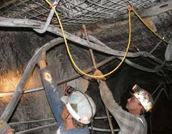
Common wiring or cabling practices make hardening of these system components difficult to achieve. Often the wiring or cable is simply hung by a tie or wire hangar from a convenient roof bolt plate, light, or rib-mounted bracket, using substantial slack to prevent over-tensioning through earth movements, thermal excursions, and repositioning of electrical components. Often manufacturers recommend slack in the 5%-10% length range. This may result in a substantial droop between hangers, meaning that an air blast of over a fraction of a bar (few psi) could sever the wire or cable. A typical cabling installation seen in mines is shown in Figure 4-2.
Cables are highly susceptible to damage from blast forces and flying debris where they cross open areas, such as where they pass in front of crosscuts. In fact, it may be more likely for the cables to fail than the devices connected to them. Sometimes the location that provides easiest access is unfortunately the most exposed to destructive forces.
One installation consideration to help improve the protection of the system is installing cables on an upper rib area rather than the roof. This is not optimal for communications coverage, but may be best for cable protection. When the cable is located in the center of the roof, there may be a greater chance for accidental damage from vehicles and other equipment. The upper rib area is considered to be better guarded by physical location.
Installing cables with slack (with or without service loops) is another installation consideration. This is a multipurpose practice in which the slack promotes better communications coverage, and the service loops allow equipment placement to be adjusted without rewiring. These practices also help the cable to be more compliant in the case of small rock falls and other incidental physical contact.
Cables can be inserted in a protective conduit. Mechanically reinforcing cables and the associated components (e.g., thicker cables, stronger covering, encasement in conduit or pipes, etc.) is especially important in critical areas of the mine. Investigating various grouting and encasement materials to protect interconnecting cabling may also increase the chances that it will survive adverse conditions.
When installing a CT system, one should also consider hanging communications, data, and power cables on the roof or rib, laying the cables on the floor, or burying the cables using trenching techniques. For trenching, it is important to consider when the trench can be dug after mining, how deep and how wide the trench should be, the type of filler material to be used, the effect of the trench on the stability of the mine floor, and how to locate and repair or replace the buried cables if needed. Installing redundant cables in separate entries also enhances survivability.
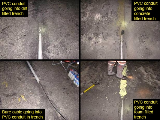
Replacing a trench with the material used to construct it is the simplest design. However, using concrete, foam, or other types of material may allow for better propagation of radio signals. Figure 4-3 provides a few examples of how to protect conductors using conduit and trenching cover techniques.
These are only a few examples of various kinds of trenches. These methods do not consider the wide variety of ground conditions in various mines, nor all types of mine floor material.
Burying the conductor at certain depths still allows for communications at both UHF and medium frequencies (MF). Figures 4-4 and 4-5 show examples of how 450 MHz and 472 kHz signals propagate in a 300-600 m (1,000-2,000 ft) mine entry when conductors are buried versus conductors being hung in the center of the entry. Burying conductors in a trench with a conduit may be very beneficial to the survivability of the conductor under vertical crushing forces and have minimal effect on the propagation of radio signals on the conductor.

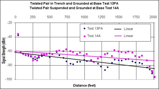
The results of these simulations (Figures 4-4 and 4-5) are only examples of possible trenching depth that may be used to provide for extra protection for certain conductors. Note that these examples are not exposed to the same dynamic loads over time that a mine environment may contain. In some cases, trenching may not be an option. Also, certain mining conditions may make hanging conductors the only feasible option.
Burying a conductor in key areas prone to damaging forces is another important consideration. This approach limits the amount of trenching while also guarding critical areas of the mine from perpendicular forces. When installing conductors, it is vital to understand the types of forces that may result from an event and their impact on those conductors.
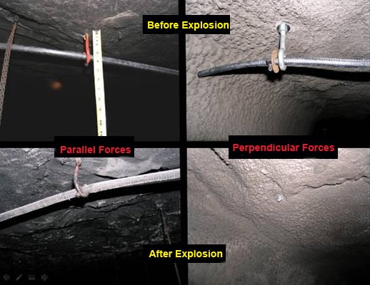
During an explosion or high-pressure wave, forces propagate down the entry like a waveguide. At tunnel intersections, these forces come into contact with conductors strung either parallel or perpendicular to the entry. Perpendicular forces are capable of destroying almost any conductor, but when the same conductor is subject to the same forces parallel to it, the damage can be significantly reduced. Figure 4-6 shows an example of leaky feeder cables subjected to a more than 8-bar (120-psi) pressure wave and shows the effects on conductors that were parallel compared to perpendicular to the pressure wave.
System Components
The primary communications system for most mines consists of hardwired mine paging phones. These systems still dominate the industry, and hardening of them will be important until other communications systems are more widely adopted. Pager phones on longwall faces would likely be mounted in a similar location as the control box (hanging down from under the shield canopy) and therefore would be vulnerable to the impact of flying coal from face outbursts. Exact locations and mounting techniques should be explored with longwall equipment manufacturers.
Coal outbursts along longwall faces can inflict considerable damage to equipment along the face. As these accidents demonstrate, consideration must be given to hardening longwall face pager phones and any atmospheric monitoring system (AMS) equipment located along the shields.
Any communications equipment not directly under vertical roof or rib falls occurring along the rib line would likely not be vulnerable to damage. Rib and roof falls in longwall headgate entries near the faces are most likely to occur along the rib lines rather than in the center of the entries due to loading from the retreating face.
System components can also benefit from the same installation techniques as used with cables. They can be recessed in a wall, floor, or roof, and/or a protective shield can be installed over them. They can be placed in cutouts and crosscuts to avoid damaging perpendicular forces. For example, amplifiers and power couplers can be located in blind crosscuts rather than open intersections. This moves the components out of the main path of travel to help prevent incidental damage. Also, being located in the crosscuts can reduce the level of blast pressure the equipment experiences during an explosive event.
Some wireless nodes may be installed in crosscuts; however, in some cases the antennas must be installed in intersections and travel tunnels to ensure proper propagation of the RF signals.
Wireless nodes should be protected in dust tight enclosures, protected against jets of water, and resistant to corrosion.
Small antennas used for frequencies greater than 900 MHz, could be enclosed in an RF-transparent dome of Lexan or some other type of polycarbonate material.
4.2.3.2 Redundancy Techniques
Redundancy is another method of increasing survivability. An example of redundancy is installing an independent leaky feeder system in an entry parallel to one already having a leaky feeder system, as discussed in more detail below.
Redundancy methods can include one or more of the following techniques:
- An alternate communications path that consists of backhaul cabling that is looped back through another portal, shaft, or a borehole to the surface. This can be applied for leaky feeder and also with network systems using backhaul cabling.
- Parallel paths assume that there are two independent conducting paths placed in two separate locations, i.e., cables and components running down two parallel entries, so that if one cable is severed or the component is damaged, the second system can maintain communications.
- Wireless mesh systems deploy a robust, self-configuring, self-healing capability of the nodes, enabling the system to reconfigure itself by rerouting (bypassing a damaged node) if one or more of the nodes fail. This can be accomplished by overlapping coverage of the nodes; however, this is often difficult to accomplish in the mine environment due to the room-and-pillar configuration.
Some hybrid systems are installed in a configuration so that both wired and wireless systems coexist in separate entries. Any weaknesses in one system may be compensated for by the other system.
Power Supplies
It is imperative that emergency or backup power supplies for CT systems work reliably when required. The reliability of emergency power supplies may be analyzed using a methodology similar to that used for CT systems.
The first step of the methodology is to define the emergency power supply system. The system engineer will identify the parameters, specifications, and requirements against which the performance of the system will be analyzed. Although some of these parameters may be the same as in routine use of CT systems, other parameters may be different. As the entire mine may be potentially explosive, the entire emergency power system must be designed to be intrinsically safe.
Alternate Communications Paths (ACP)
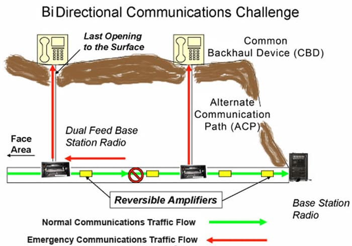
Alternate communications paths (ACPs) involve communications and/or electronic tracking system links to the surface at locations that are remote from the MOC. ACPs may use a specially drilled borehole, separate air shafts or any other method of access to the surface separate from the main entries. Ideally, there would be an RF communications path on the surface from an ACP back to the MOC, so that information between the ACP access point and the MOC would be relayed with a minimum of delay. In the optimum system, messages and information would be relayed automatically. However, the message relay could be done manually by operators stationed at the ACP surface egress point (i.e., any message to/from the ACP egress point is received and repeated by the operator). The link should only be required in a rare emergency in which the normal backhaul has become inoperable. Measures should be taken to ensure the ACP access point is easily reached and periodically verified that it is operational. CT systems that use an ACP must be capable of reversing the direction of message flow, at least over a portion of the backhaul system.
Figure 4-7 shows an example of an ACP layout with the bidirectional area of communications. The green line shows the normal way that communications traffic will flow. The red line shows the alternative emergency communications way if the normal communications were disrupted by a blast, fire, or roof fall in the mine. There are two ACPs within this system. Depending on how far the miner is in the mine he can use either one of the ACPs. When the communications path reaches the open surface there is a common backhaul device (CBD) at each surface location.
4.2.3.3 Hardening and Redundancy Considerations for Electronic Tracking Systems
Most tracking systems share the backhaul with the communications system, so redundancy and hardening improvements made to the communications system also directly benefit the tracking system.
A tracking system’s redundancy can be further improved by adding more location tracking reference points. Depending on the type of tracking system, the reference point may be an RFID reader, an RFID tag, or a wireless access point (WAP). The more tracking reference points installed in a mine, the more accurate the system, plus it allows the system to provide tracking information even if one or more of the reference points are lost.
4.2.3.4 Hardening and Redundancy Considerations for Atmospheric Monitoring System (AMS)
Manufacturers of atmospheric monitoring systems (AMSs) (i.e., systems that measure one or more types of mine gases such as methane, carbon monoxide, etc.) have indicated that there are no industry requirements for a redundant AMS system. Therefore, mine operators generally do not request system redundancy. However, some leaky feeder and wireless systems do offer add-on AMS equipment which would then benefit from the redundancy of those systems.
AMS sensor manufacturers have indicated that it is difficult to harden AMS sensors, as they need to be able to freely sample the air and to be placed in high-use areas of the mine.
True mine-wide AMS systems do not yet exist in most mines, so it will be important to protect those systems that detect fires and other hazardous, flammable, and noxious gases along beltlines until more complete systems are widely adopted.
4.2.3.5 Reconfiguration Techniques
Reconfiguration refers to the ability to create redundant routes in a network by adding nodes or changing to a different communications technology. An example of the latter is switching channels on a hand-held radio after a leaky feeder becomes inoperable. The new channel would link the hand-held radio to a media converter device interfaced to the hardwired pager phone. This action creates a redundant path, but only after some feature of the system is reconfigured. The redundant path increases the survivability of the system. Similar to the redundancy discussion earlier in this chapter, the increased number of components will decrease the basic reliability. However, the additional message routes will increase the operational reliability.
4.2.4 Calculation and Modeling
The military and automotive industries are examples of institutions that have well-established reliability programs and standards. Over the years, they have developed powerful methods and tools for calculating survivability and reliability of systems. It is highly recommended that these methods and tools be tailored for use in the mining industry and for CT systems in particular.
All the tools for calculating survivability and reliability require developing a model to describe the CT system. For example, for each communications system discussed in Chapter 2, a block diagram of the main components was presented. The block diagram is one type of model of a system. It is possible to calculate reliability numbers that can be associated with each block of the system. A systems engineer can then evaluate how changes to a particular block can affect the overall system reliability.
For example, Figure 4-8 shows a block diagram of a leaky feeder system with a splitter, after which there are two leaky feeder cables in parallel, one terminated with an antenna and the other with a termination unit. Two separate radios are able to link to either of the two leaky feeder cables. The reliability of each component is shown as a percentage number below the block.
![Figure 4-8. Block diagram of portion of leaky feeder showing percentage reliability of each component [QinetiQ 2008].](../../../UserFiles/content/emergencymanagementandresponse/commtracking/commtrackingtutorial2/4-8.png)
of each component [QinetiQ 2008].
All the components in Section 1 of Figure 4-8 are in series. Hence if one component fails, the entire system fails. The basic or, in this case, the operational reliability of Section 1 is found by multiplying together the reliability of the six components:
Section 1 reliability = 0.98 x 0.97 x 0.98 x 0.96 x 0.98 x 0.95 = 0.83 or 83%.
Notice that the reliability of a series system is less than any of the components.
Section 2, inby the splitter, shows the two leaky feeder cables as parallel components. As redundant cable systems, it assumes if one cable fails, the other will maintain the operations. The operational reliability of components in parallel is found by adding the reliabilities of the parallel systems and then subtracting the product of the reliabilities of the parallel systems.
Reliability of upper cable = 0.98 x 0.96 x 0.98 x 0.98 = 0.90
Reliability of lower cable = 0.98 x 0.98 = 0.96
Section 2 reliability = 0.90 + 0.96 - [0.90 x 0.96] = 0.996 or 99.6%.
Notice that the operational reliability of systems in parallel (upper cable is in parallel with lower cable of Figure 4-8) is greater than either system alone, i.e., 99.6% is greater than 90% or 96%.
A similar analysis can be performed to get a reliability percentage in Section 3 of 99.6%.
The total operational reliability for the system shown in Figure 4-8 is the product of the reliabilities of each section:
Total system reliability = 0.83 x 0.996 x 0.996 = 0.82 or 82%.
With this type of model, it is possible to perform "what if" types of analyses. For example, if the lower cable with the termination unit were not part of the total system, the reliability of the system would become:
The total system reliability without the lower cable = 0.83 x 0.90 x 0.996 = 0.74 or 74%.
The reliability with the redundant or parallel system has a higher operational reliability of 82% compared to the system without the redundant path, 74%. This quantitatively illustrates the benefit of having a redundant communications system.
Similar modeling and calculations can be established for determining survivability.
4.3 Availability
A simple equation for determining availability is:
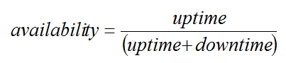
In a more rigorous discussion, the mean time between failures (MTBF) is used by a manufacturer to describe the mean (average) time a system or component is expected to operate before a failure occurs. Similarly, the mean time to repair (MTTR) is the average time used to repair a failed system or component. With these definitions, the availability can be expressed as:
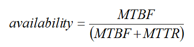
From Equation 2, it can be seen that a system could have a low reliability (MTBF) and still have a high availability if the MTTR is small relative to the MTBF. The MTTR can be estimated from knowledge of the accessibility of spare parts, and how the repair of the system is manned. For example, is the repairman onsite 24 hours a day or only during regular working hours, or possibly only on-call?
Availability is easily understood by considering downtime. Availability is typically specified in "nines" notation; a 3-nines availability corresponds to a 99.9% availability. Table 4-1 shows the relationship between availability and downtime.
| Availability | Downtime |
|---|---|
| 90% (1-nine) | 50,000 minutes/year |
| 99% (2-nines) | 5,000 minutes/year |
| 99.9% (3-nines) | 500 minutes/year |
| 99.99% (4-nines) | 50 minutes/year |
System availability may be calculated by modeling the system as an interconnection of parts in series and parallel. Figure 4-9a shows two systems or components in series. The parts are considered to be connected in series if a failure of either leads to the system becoming inoperable. Figure 4-9b shows two systems or components in parallel. The parts are considered to be connected in parallel if a failure of either leads to the other taking over the operations of the failed part.
The availability of a system composed of Parts X and Y in series is the product of the availabilities of the two parts. So if the availability of Part X is 99% (downtime = 5,000 minutes per year, or 83 hours) and Part Y is 99.9% (downtime = 500 minutes per year, or 8.3 hours), the overall availability for the series combination is 98.9% (downtime = 5,700 minutes per year, or 96.4 hours). When parts are combined in series, the overall availability of the combination is less than the smallest availability of the individual parts.
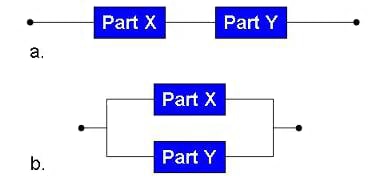
If a system is composed of parts X and Y in parallel, the system is operational if either part is available. Hence, the combined availability is calculated as 1 (the probability that both parts are unavailable). Using the availabilities given for the parts in the example above, the overall availability for the parallel combination becomes 99.999% or 5.2 minutes per year. When parts are combined in parallel, the overall availability is greater than the highest availability of the individual parts. This is a very powerful method making highly reliable systems, and illustrates why critical systems are designed with redundant components.
- The Emergency Communication Triangle
- Emergency Communications and Tracking
- Passive Fiber Optic System for Locating, Tracking, and Communicating with Personnel in Coal Mines
- Survey of Electromagnetic and Seismic Noise Related to Mine Rescue Communications: Volume I - Emergency and Operational Mine Communications
- Survey of Electromagnetic and Seismic Noise Related To Mine Rescue Communications: Volume II - Seismic Detection and Location of Isolated Miners
- System Reliability and Environmental Survivability
- Technology News 507 - NIOSH Safety Talk: The Emergency Communication Triangle
- Technology News 543 - Reverse Implementation of Radio Frequency Identification (RFID) Technology for Personnel Tracking in Underground Mines
- Technology News 546 - Medium Frequency Mine Emergency Communications - An Emerging Technology
- Training to Improve Emergency Communication Skills