Advanced Tutorial on Wireless Communication and Electronic Tracking: Electronic Tracking Systems Performance
3.0 Electronic Tracking Systems Performance
The 2006 MINER Act requires that electronic tracking systems be in place at coal mines to facilitate rescue operations in case of an emergency. Electronic tracking systems provide a mechanism for surface personnel to know which workers are in the mine and in which area they are working.
Many mines use manual tracking to monitor which miners are underground and their general location. When using manual tracking, at the beginning of each shift, the mine foreman provides the dispatcher with a list of names of people and where they are going within the mine. Once in the mine, if a miner needs to go to a different area to work, he notifies the dispatcher using the dial phone in the mine. The dispatcher then updates the list of miners’ current locations.
Manual tracking has a number of limitations. A miner’s location may be given as being within a working section that can be quite large and therefore difficult to pinpoint a miner’s exact location. Occasionally a mine worker will forget to notify the dispatcher when moving to another work location.
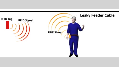
Several electronic tracking technologies that overcome the limitations of manual tracking are currently available. One technique uses a reader-based technique called radio frequency identification (RFID) technology. One common implementation of RFID technology can be found in retail stores to prevent merchandise from being stolen. In this type of system a small electronic circuit called a tag is attached to the merchandise. At the store’s exit, two vertical gates periodically emit a radio frequency (RF) signal. The signal is received by the tag attached to the merchandise, and the circuit emits a return RF signal if the tag has not been deactivated at the cash register. The return signal from the tag is picked up by the vertical gates and a warning is sounded. These systems use ultralow-cost and very short read range tags. Many industries use the tag-and-reader approach for tracking items and equipment. There are many types of tag-and-reader systems. Each system is optimized to trade off parameters such as read range, cost, reliability, and robustness. Examples of RFID tags and readers are shown in Figures 3-1 and 3-2.
A second type of tracking technology (node-based electronic tracking) uses the communications link between a radio and a node. The node analyzes the radio signal strength from a miner’s radio to determine how far away the radio is from a node (or multiple nodes) to estimate the miner’s location.
Another technology that has been proposed for use in mines is called inertial navigation (or inertial guidance). The system measures accelerations and other motion characteristics of the miner to determine how far the miner has moved from a known starting point.
In addition to determining location, there are other important characteristics for tracking systems. The system must have the system capacity to track the maximum number of people that may be in a coverage area. It must also be able to distinguish each individual in a group of workers traveling in an area of the mine at varying speeds, e.g. walking or riding in a vehicle. In addition, there may be a requirement as to how often the tracking system needs to update each miner’s location, referred to as the scan rate. All of these features should be discussed with a vendor when considering the purchase of a tracking system.
3.1 Tracking Techniques
As mentioned above, several tracking technologies are available for use in the coal mine environment. One technology, reader-based tracking, is similar to what is used in retail stores. It has two major components: a device called a reader for detecting the presence of tags and the tags themselves. In a retail store the tag will be what is called passive, in that it does not contain a battery. Typically, however, in mining the tag will be what is called active, in that it contains a battery. In mines, there are two variations within the reader-based technique. In one approach, called zone-based RFID, a tag is placed on each miner and the readers are installed at specific locations within the mine. In the other approach, called reverse-RFID, each miner wears a small reader and the tags are installed at known locations within the mine.
Another technique (node-based tracking), does not use tags. It relies on a sophisticated analysis of the RF signals passing between a radio and one or more nodes to determine the distance of the radio from the nodes.
The last tracking technology to be discussed is called inertial tracking, which uses sensors worn by a miner to monitor accelerations, changes in the earth’s magnetic field, and changes in angular rate of the miner to calculate the change in the miner’s location. The miner’s location would be calculated from these changes, either by a small computer worn by the miner, or the change information can be transferred to a central computer at the mine operations center. In either case, a link to the communications system would be required to report the location information to the surface. As of this writing, inertial tracking systems are still under development, and thus the discussion of this technology in this tutorial is limited.
In the following sections, each of these tracking technologies is discussed in more detail.
3.2 Reader-Based Tracking
Reader-based tracking is implemented in one of two forms: 1) zone-based RFID, in which case the miner wears the tag and the readers are in predetermined, fixed locations; or 2) reverse-RFID, in which case the miner wears the reader and the tags are in predetermined, fixed locations.
Reader-based tracking systems merely detect when a tag and a reader are within RF range of each other. When a tag is recognized by a reader, the miner’s position becomes associated with the location of the fixed component (tag or reader). The resolution or distance within which the miner is located is determined by the spacing between fixed-position components. In some systems, a received signal strength indicator (RSSI) is used to further increase accuracy. These topics will be explained in more detail below.
3.2.1 Zone-Based RFID
3.2.1.1 Description
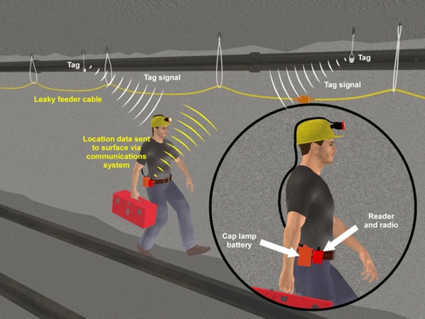
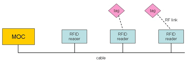
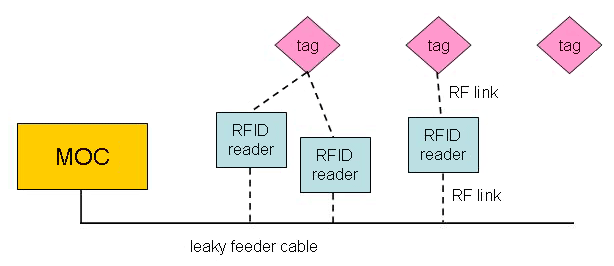
Zone-based RFID is based on readers positioned in known locations within the entries, and each miner wearing an RFID tag. Each miner wears a tag that transmits a unique identifier that has been assigned to that miner. The tag is read whenever the miner passes within the RF range of a reader. The reader transmits an RF signal to which the tag responds. The reader is said to interrogate the tag. Upon receiving the return signal from the tag, the reader must relay the detection information to a central location, usually the mine operations center (MOC). The information can be relayed a number of ways, e.g., over a pair of wires, through fiber-optic cable, via wireless communication, or through an interface to the communications system backhaul.
Each RFID reader has a unique identification and a location associated with that identification, so that when a tag is read by a given reader and the information is forwarded to the MOC, personnel at the MOC know that the miner is within a certain radius (the RF range) of that reader’s location. Because the miner’s location is determined to be within the RF range of the reader, this is referred to as zone-based RFID.
Figure 3-3 shows two miners wearing tags whose RF range is indicated in red. The fixed position readers have an RF range indicated by the blue ovals. Miner A is within RF range of the reader located at survey marker 58301. A representative RF range is about 100 m (300 ft). Thus, miner A is known to be within 100 m (300 ft) of survey point 58301. This could be displayed as text or on a mine map on a computer terminal in the MOC.
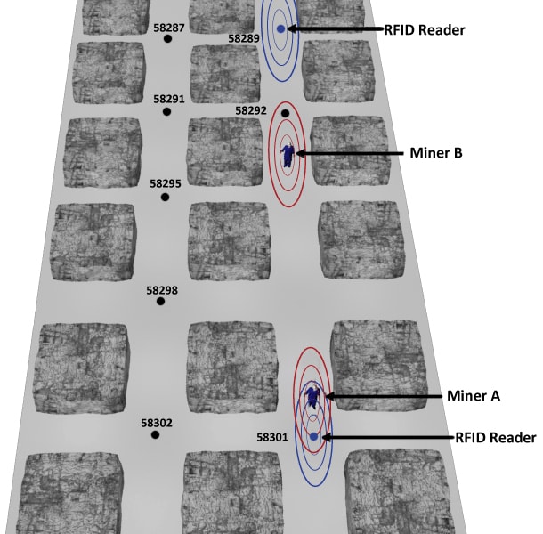
Miner B, who is walking toward miner A, is not within RF range of any reader. With zone-based RFID, unless the zones overlap, there are situations in which a miner’s location is not known for certain. If Miner B had recently been within range of the reader at survey point 58289, then the display in the MOC might have a special indication that Miner B had been at 58289, but was not within range at this time. It could also display the last time and location that a reading had been recorded for that miner.
Notice that Miner A could go down the left or right crosscut at survey point 58301, and he would still be considered to be within 100 m (300 ft) of point 58301. Miner A might be part way down a parallel entry and still within 100 m (300 ft) of 58301, except that the RFID readers generally require a line-of-sight (LOS) to read a tag. To resolve the miner’s position and know his location more precisely, more readers are needed, which increases the cost of the RFID system.
There are other performance factors for RFID tags and readers that should be evaluated. In reading a tag, there is a certain probability that an incorrect reading or no reading will occur. The uncertainty in reading the tag can be due to several factors:
- The distance between the tag and reader (greater distance yields a weaker signal making it more difficult to interpret).
- Orientation of the tag relative to the reader (e.g., if the plane of the tag is oriented normal to the reader, it does not receive an interrogating pulse).
- The presence of metal objects (metal may reflect incident RF signals, confusing the reader or the tag).
- The presence of multiple tags close together (multiple tags on a group of miners may confuse the reader because of multiple superimposed signals).
Another performance feature is the frequency of the reads (i.e., how often the system updates the readings). The frequency of updates can also affect the power requirements for the system and the life of the battery.
3.2.1.2 Components
The main components of a zone-based tracking system are the tags and the readers. The tags are typically inexpensive, but the readers are typically expensive. The tags are battery operated, but are low-power devices. The batteries should be expected to last for several years before needing to be replaced.
The readers operate on mine AC power under normal conditions. In case of an emergency, they will use battery backup power. The readers also need a mechanism to get their information back to the surface, with the most likely location on the surface being the MOC. The information from the readers can be transferred to the MOC over wired or wireless links dedicated to the readers. Another alternative is to link the reader into the communications backhaul system to send the information to the MOC. Appropriate software and a computer with a display monitor are required at the MOC to interpret the information being sent by the readers.
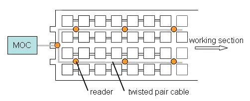
Figure 3-4 illustrates a block diagram of a zone-based tracking system with a hardwired backhaul system to the MOC. The tag might be worn on the miner’s helmet. A twisted-pair cable is used to transfer the RFID reader information to the MOC.
3.2.1.3 Transmission Media
Reader-based tracking systems must establish a physical RF link between the tag and the reader similar to a communications link so that the tag and the reader can exchange RF messages. A link budget analysis can be performed on the system to verify that it will function as intended.
Figure 3-5 shows a miner wearing an RFID tag on his helmet. An RFID reader is mounted in the entry. There is a downlink from the reader to the tag, and an uplink from the tag to the reader. A link budget analysis should be performed on both the downlink and uplink to ensure the received power in each case is above the receiver signal level threshold of the tag and reader, respectively. The difference in analysis between the uplinks and downlinks is in the transmit powers of the reader. The reader and the tag have different transmit powers.

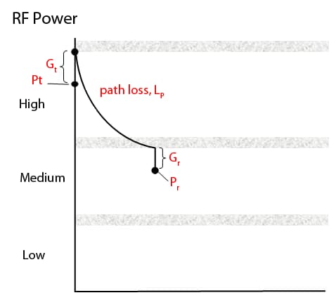
The downlink budget analysis is shown in Figure 3-6. (The uplink analysis can be done in a similar manner.) The link budget analysis begins with the reader transmit power Pt at the left of the graph. The reader is assumed to have an antenna with positive gain Gt adding to the transmitted power. The transmission medium is air, and the associated path loss is Lp. The RF signal is picked up by the tag antenna which has a gain Gr, assumed to be negative, and thus the power is reduced. The resulting received power is Pr. Most of the values used in this link budget analysis can be obtained from the manufacturer.
3.2.1.4 Network Operations
Similar to communications networks, there are two aspects to the electronic tracking network: access and transport. The tags access the network through a reader, using the air as the medium for the RF signal. The reader transports the information to the MOC. There are a variety of ways that the reader information can be transferred to the MOC.
Figure 3-5 uses a twisted wire pair to form the backhaul to the MOC. In this case, the readers are likely to be in a linear topology, or if multiple entries are wired, a tree topology might be used as shown in Figure 3-7. However, a more survivable approach would be to use a ring configuration or an alternate communications path out of the mine.
The readers can also be integrated into the backhaul system if the systems are compatible. For example, if there is a leaky feeder system is being used for the backhaul system, the RFID readers can use the leaky feeder cable to get the location information to the MOC by acting as a radio repeater and thereby establishing an RF link with the leaky feeder cable. The tracking network topology would then be the same as the communications system topology.
It is unlikely that the RFID readers would be integrated into a node-based communications system network because, as will be seen in Section 3.3, node-based communications have an inherent ability to perform tracking; consequently there is no need for RFID readers or tags.
3.2.1.5 System Implementation
The tracking system can be implemented independently of the communications system. Both the tracking and communications systems could have separate links to the surface, but it may make sense to integrate both systems. It is most likely that tracking will be required in the same entries and strategic locations as communications.
Zone-based RFID tracking systems differ primarily by:
- The method used to transmit tag data back to the MOC.
- The method used to transmit data between the reader and the tag.
- The location of the tag on the miner.
To transmit data back to the MOC some tracking systems use a dedicated communications system while others use whatever communications system is already installed. Whether or not the tracking system is integrated into the communications system, implementation recommendations are dependent on the specific communications technology (as covered in Chapter 2). Tags that are integrated into another piece of equipment, such as a cap lamp battery, do not need any adjustments or special care of any kind to be detected by a reader. Tags that are separate units need to be worn so as to be detected by the reader. The manufacturer of the system is the best source of guidance for protection of their hardware. The only caution is that active tags (tags that require a battery supply) are miniature transmitters. While their power output is small, they can be worn very close to vital organs and are likely to be worn for long periods of time. The amount of output power and distance from the body should conform to safe distance recommendations (see Section 5.3.1).
Readers are complex electronic devices that must be protected from damage by mounting them out of the way of moving equipment. At the same time they must be able to "see" the tags to operate correctly. It is possible to recess readers into the mine’s ribs to protect them from blast forces, but this will likely reduce their RF range. Generally, the readers require line-of-sight to the tags, and recessing a reader will reduce its field of view. A reader may be located at a crosscut to increase its coverage, but such a location may be more susceptible to blast forces and roof falls. As discussed below, installation at a crosscut can also cause location errors or uncertainty under some circumstances. Attention should be paid to protecting connecting cables and connectors. The manufacturer is the best source of information on how the reader must be installed.
The loss of a single reader does not result in the failure of the system. Because the last known location of the miner is always stored by the system, a location estimate can still be made even though the miner is not within range of a functional reader.
Spare tags should be readily available for quick replacement of damaged units because a failed tag means a miner cannot be tracked. The tracking software at the surface should allow for quick reassignment of tag IDs. If the tag is integrated into the cap lamp battery enclosure, then the complete unit may have to be replaced. If tags use replaceable batteries, spares should be readily available.
3.2.1.6 Maintenance and Inspection
RFID systems are in common use in many fields outside of mining and their operating characteristics are well understood. However, the underground mining environment adds an important complication in regard to the tag-to-reader detection range. The nominal tag/reader detection range will depend on physical locations of the readers and the tags in the mine as well as the mine geometry. It is unlikely that the detection range will be the same for all readers. In addition, equipment can block the line-of-sight between a reader and a tag, exposed antennas can be damaged, batteries can discharge, and electronic components can age. All of these factors can affect the tag/reader detection range. The system may have the ability to monitor the battery condition of its components, but other factors are not as easily assessed. As a result, the system performance, in particular the detection range, can only be verified by periodically testing critical underground locations.
Tag readers usually have indicator lights on the units which provide information about their health status. Some may signal the MOC when an error is detected. The only certain way to know if the system is working is to periodically test each reader by allowing it to read a tag and cross-check the result at the MOC. A good test would be to have a miner walk a predetermined route and record the time at certain points of the route. Comparing the known route and time data to the recorded data provides the check. Because readers are designed to read multiple tags in rapid succession to accommodate groups of miners or miners riding a man trip, the more advanced features cannot be easily checked unless there are built-in diagnostics. These tests, if available, should be run as recommended by the manufacturer.
Replacing tags that have failed requires reprogramming the tracking software to connect the new tag ID with a particular person. Maintaining the system’s database to reflect tag replacement is critical to performance and a standard replacement routine should be followed. Tests also need to be carried out as required by federal and state regulations in addition to the manufacturer’s guidance.
The tag may also have an indicator light to alert the user of a malfunction. However, the simplest test is to allow a reader to read the tag and see if it was detected correctly.
3.2.1.7 Performance & Limitations
In this section, tracking coverage area refers to the area of the mine in which the tracking system can provide location information about a miner. While tracking systems are limited by their dependence on a backhaul system to send data to the MOC, RFID systems are further limited by the reader/tag detection range and the distribution of readers. The latter two limitations will be discussed in more detail.
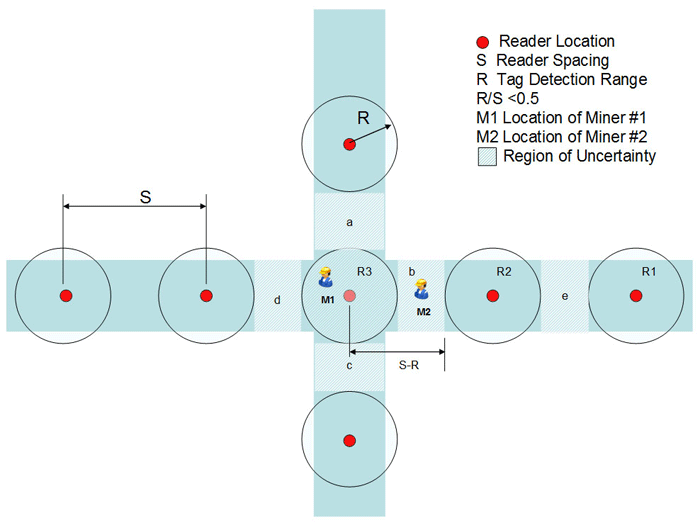
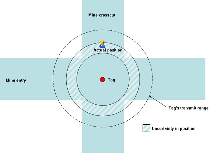
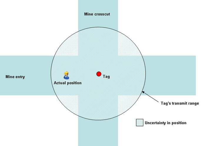
The usual definition for accuracy gives the location uncertainty in meters (feet) for a detected tag. A reader can detect whether or not a tag is within its detection zone, but not where it is within its zone. Figure 3-8 provides a demonstration. The reader spacing is "S" and the reader can detect a tag within a radius of "R". For a miner in position M1, the system reports his position to be within ±R of reader R3. So the location accuracy of M1 is ±R. In contrast, a miner in position M2 is not detected by any reader, but if he were previously detected by reader R3, then there are four areas he could have walked into (a, b, c, or d). If he were last detected by reader R2, he could be in areas (b) or (e). In both cases, he is within a circle of radius S-R, which, depending on the reader spacing, may be much greater than R. For widely spaced readers, accuracy varies greatly between detected and nondetected miners.
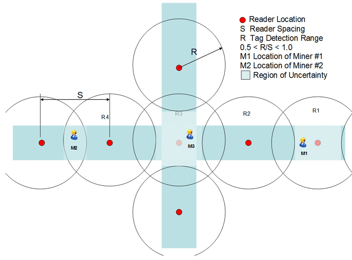
When the reader detection ranges overlap (Figure 3-8), this problem does not occur. The accuracy depends only on the distance between readers and is no worse than ±S/2 at the time of detection. The tracking software must be able to calculate the miner’s position based on detection by multiple readers. However, accuracy is still limited by the interval between system updates. For example, a miner walking at about 3 km/hr (2 miles/hr) would travel 50 m (175 ft) in one minute. Consequently, one minute after detection, the miner could be 50 m (175 ft) from the last known reader detection zone in either direction. To meet a given accuracy requirement, reader spacing, detection range, and update interval must all be considered.
As mining progresses, the system will need to be expanded to allow coverage in new areas. For a typical system, this will involve installing new readers in the mine and associating them with survey markers or landmarks, such as an intersection. The new reader information is then input into the tracking software database. New miners must be issued individual tags and the tag ID must be entered into the tracking database. Maintaining an accurate database of readers and tags is a critical requirement.
Critical functions of the tracking system include tracking the location (with time stamp) of all miners while underground, providing data storage capabilities so location history for each miner is available, providing diagnostics for identifying damaged units, and monitoring the condition of the tags’ batteries. Both the surface and underground portions of the tracking system should be equipped with standby power to ensure continuous operation in the event that the line power is interrupted. The tracking system should be configured to allow monitoring of the location of miners underground from the communications facility required under 30 CFR. § 75.1600-1, which also requires that someone on the surface should always be on duty when miners are underground. The tracking system should also include the capability to display the location of all miners underground at all times. In addition, the tracking system interface should display the last known location of a miner when the tracking device is not communicating with the system.
Survivability of the tracking system after an accident is another key requirement of the MINER Act of 2006. RFID systems may either use the existing mine communications system or a dedicated system to transmit location information to the surface. In either case, the survivability of the tracking system is tied to the survivability of the backhaul system. If the backhaul system is damaged during an accident and cannot be restored during rescue efforts, the tracking system will not provide updated miner location information. Only the last known position of each miner before the accident will be available. If system components must be installed in areas vulnerable to damage, such as in front of mine seals, protection should be provided against forces that could cause damage. Protection could be provided by installing hardened enclosures in recessed areas, around corners, or other areas that can help to reduce the potential for damage.
In the event that mine power is lost during an accident, it will not affect the operation of the tags because tags normally operate on internal long-life batteries or are integrated into the miner’s cap lamp assembly. Readers are required to have battery backup capability and are expected to operate for more than 24 hours if properly maintained. Currently available systems exceed this requirement.
Miner location data is generally only available on the surface tracking computer, but the tag worn by the miner is continuously sending out its ID. Although this signal has a limited range, typically less than 150 m (500 ft), a rescuer with a portable version of the reader might be able to use the signal to further aid in finding trapped miners.
3.2.2 Reverse-RFID Tracking
3.2.2.1 Description
Zone-based RFID tracking has been described in Section 3.2.1. In zone-based RFID, each miner wears an RFID tag and the readers are in fixed, known locations. In reverse-RFID tracking, the miner wears the reader and the tags are in fixed, known locations. An advantage of this approach is that RFID tags are inexpensive. Tags can be located close together to achieve greater precision in locating the miner compared to zone-based systems, where the readers may be located fairly far apart to keep costs down.
The location information obtained by the RFID reader, which the miner is wearing, must reach the MOC. To accomplish this, the reader has a radio transmitter that periodically transmits the miner’s location data to the mine’s backhaul communications system. Figure 3-10 illustrates a reverse-RFID system in which the backhaul is a UHF leaky feeder system.
The RFID tag is programmed to periodically transmit its identification information, shown in red in Figure 3-10. A separate antenna might be mounted on the miner’s cap to receive the RFID tag signal. The RFID information is then transferred to the transmitter on the miner’s belt to be relayed to the leaky feeder cable and ultimately to the MOC. A UHF transmitter mounted on the miner’s belt transmits the location information to the leaky feeder cable.
3.2.2.2 Components
The reverse-RFID tracking system has the same components as the zone-based system: tags, readers, some type of backhaul communications to the MOC, software, and a computer with a monitor. In the reverse-RFID system, the RFID reader must have an RF transmitter to relay information from the miner to a network that acts as the backhaul to the MOC. Although the components are similar to the zone-based RFID system, the block diagram of the reverse-RFID system is quite different (see Figure 3-11).
Each tag has a unique identification number and a unique location within the mine. The tags are battery operated, but battery life is estimated at several years. The readers are worn by the mine workers. Each reader is unique and assigned to a specific miner. The readers are battery operated, but they can be recharged when the miner is not working.
Because a leaky feeder cable provides communications coverage essentially in the entry in which it is located, the tags and the RFID readers (on the miners) would also have to be in the same entry for the system to provide useful location information. Leaky feeder coverage, and hence, reverse-RFID tracking coverage, can be extended into parallel entries or isolated locations though through the use of an antenna that is spliced into the leaky feeder cable (see Figure 2-15).
3.2.2.3 Transmission Media
As seen in Figures 3-10 and 3-11, two physical RF links must be established for the reverse-RFID connection, although the links need not be established simultaneously. One link is between the tag and the reader, and the second link is between the reader and the backhaul network, in this case assumed to be leaky feeder. Both these links are through the air and both could have uplinks and downlinks.
Consider the physical link between the tag and the reader. The reader may send an interrogating signal to the tag and the tag will respond. Thus, there is an uplink and a downlink. Alternatively, the tag may periodically transmit its location information which is received only when a reader is within range and not required to have an interrogating signal. In this case only a link in one direction is required. The disadvantage of the single-link approach is that the tag is continually transmitting, which requires power from the internal battery. In the first approach, the tag is inactive until it receives an interrogating pulse. It should therefore use less energy as compared to the latter case, and the batteries should last longer between replacements.
It is required that the reader link with the backhaul to be able to send its location information to the MOC. There is no requirement to establish a link in the opposite direction (backhaul to reader). It may be a good safety measure though to have the MOC periodically send a signal to the reader indicating that there is a connection to the MOC. The miner’s reader could have a reassuring light to indicate that a link to the MOC is present. The link could also be used for the MOC to verify that a connection to the miner is present.
A link budget analysis would normally be performed for all uplinks and downlinks to verify that the receiver signal level threshold was met for each receiver. For simplicity, the analysis below only considers the links from the tag to the reader and from the reader to a leaky feeder cable. Figure 3-12 illustrates the link budget analysis beginning with the tag transmitter power Pt of the tag at the far left of the graph. The gain of the tag antenna (Gtag), is assumed to be negative. The path loss for the RF signal through the air is Lp1. The negative gain of the reader’s receive antenna is Gr1, resulting in a received power in the reader of Pr reader.
The reader will change the frequency before retransmitting the location information at power Pt reader from its antenna of gain Gt reader. There is the path loss of this signal through air Lp2 as it is received by the leaky feeder cable which has an assumed gain of Gr cable. The received power in the leaky feeder cable is Pr cable. Most of the values used in this link budget analysis could be obtained from the manufacturer.

3.2.2.4 Network Operations
As discussed in the previous section, the reverse-RFID system uses RFID tags distributed throughout the mine at specified locations. Each miner wears his assigned RFID reader. The reverse-RFID system requires an existing backhaul communications system to transmit the location information to the surface, and ultimately to the MOC. The reverse-RFID reader must transmit location messages that are compatible with the backhaul system.
As included in the discussion of communications systems in Chapter 2, the reverse-RFID reader is not compatible with wired communications. An interface to a wired communications backhaul would have to be wired, and the reader must be untethered to meet the requirements of the MINER Act. The reader could be designed to communicate, for example, with a VHF or UHF leaky feeder or with a UHF node-based system. A leaky feeder backhaul has been used in most of the examples in the earlier sections on reverse-RFID, however that does not preclude the use of other technologies. It is unlikely that the reader would transmit medium frequency (MF) to couple to an MF network because the MF antenna and transmitter are too bulky. The reader could transmit VHF or UHF and couple to an MF/VHF or MF/UHF converter and ultimately to a digital MF network. Regardless of the technology used, the network backhaul will likely be that of the communications system. The reverse-RFID reader would represent an additional access to that network.
3.2.2.5 System Implementation
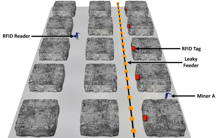
The reverse-RFID tracking system requires a communications backhaul system to relay location information to the MOC. Figure 3-13 shows a leaky feeder system providing the backhaul to the surface of the mine. In this example, there is an RFID tag on each pillar in the entry with the leaky feeder cable. If Miner A is within RF range of an RFID tag, his position can be read and transmitted to the leaky feeder cable by the reader. In the MOC, the miner’s location would be associated with the known location of that tag. Therefore, if the crosscuts are separated by 30 m (100 ft), then the miner’s location would be known to within 30 m (100 ft), provided the miner remains in the entry with the leaky feeder cable. Signal strength measurement techniques, such as RSSI, can further improve accuracy by estimating distance from a tag based on the strength of the received tag signal.
For the reverse-RFID system to remain viable after an accident, the backhaul, RFID readers, and tags need to be operational. Because the reverse-RFID system is dependent on the backhaul system, the survivability of the RFID system will depend on the survivability of the backhaul. Thus, any provisions to harden the backhaul or accommodate alternate communications paths will also increase the survivability of the tracking system.
If the miner survives an accident, there is a good chance his RFID reader also survived. However, after an accident involving an explosion, fire, or a roof fall, one or more tags may be damaged. The failure of a tag will result in less tracking accuracy in the immediate area of that tag. As soon as the miner reaches the next operational tag, the accuracy is then restored to normal. If multiple adjacent tags are not functioning in an area, tracking may not be possible until the miner reaches the transmit range of the next properly functioning tag. The last known location of the miner is always stored by the system so that a location estimate can still be maintained.
RFID tags may be recessed into an entry wall or covered with a nonconducting shield to protect them against blast forces. Recessing a tag may decrease its field of view and thus, reduce its RF transmit range. To minimize the chances of being struck by equipment, tags may need to be hung near a wall rather than the center of an entry or in the middle of an intersection. Each manufacturer will list minimum clearance distances between tags and other structures.
For the highest resolution and redundancy, tags should be attached to the roof with a spacing between the tags less than or equal to the maximum transmit range of each tag. This provides 100% overlap of the tag signals. In areas where less resolution is needed, greater spacing can be used. Tags can be hung at intersections to allow tag detection in crosscuts, although the detection range and ability to communicate with the backhaul system will limit the distance a miner can travel into a crosscut and still be tracked. Tag density may need to be increased in working sections to increase both accuracy and redundancy.
Hardening of the reader electronics is maximized when the reader and backhaul radio are integrated into the cap lamp battery enclosure and existing cables. In some systems, the reader electronics and radio may be in separate enclosures and worn on the belt. This presents more failure modes as cabling, separate power supplies, and an extra enclosure all add complexity to the system. Hardening of the cables, connectors, and enclosures is critical, and methods should be employed to route and bundle cables so that they are not a hazard to miners.
It is recommended that spare tags be readily available for quick replacement of damaged or failed tags. The tracking software at the MOC should allow for quick reassignment of tag IDs. If the tag reader and radio electronics are integrated into the cap lamp battery enclosure, then the same recommendation for spare cap lamps located underground should apply. If the tag reader electronics are in a separate enclosure, spare reader units should be available underground. If a miner replaces his reader unit while underground, surface personnel must be notified so that the tracking software is updated. The new reader ID must be entered and its operation verified, and the old reader ID must be removed from the tracking system database. Bookkeeping procedures must be well-established to prevent errors that could result from a tag reader being replaced with another reader unit.
3.2.2.6 Maintainability and Inspection
The complexity of reverse-RFID systems is generally considered high due to the number of tags required throughout the mine, the addition of a tag reader device that must be worn by each miner, and the required interface to the existing mine communications system. The system’s tracking computer should have a maintenance function that will automatically run self-diagnostics at predetermined intervals as well as have the option to manually initiate diagnostic scanning. Maintenance for the tracking computer will be similar to normal maintenance provided for all computer-based equipment (e.g., antivirus updates, software updates).
Tags can fail during day-to-day operations due to low-voltage batteries, physical damage from passing equipment, and harsh environmental conditions (moisture, dust, humidity, etc.). For these reasons, tags must be visually inspected at regular intervals. This can be accomplished during other mine inspections and safety checks and should occur at least quarterly. Along with a visual inspection, the functionality of each tag should be checked periodically by verifying that the software is correctly updating the inspector’s location as the system is being inspected. In addition, some systems will flag a particular tag if it has not been detected by a reader in a predetermined amount of time. It would be useful to have a test station at the entrance to the mine to verify that the miner’s reader is working properly before the miner goes underground. Also, a portion of the message stream that is transmitted to the reader from the tag should include tag battery status. Maintenance personnel can then be alerted by the software to investigate the operation of a particular tag and determine if it should be replaced with a new tag.
3.2.2.7 Performance and Limitations
The performance of a particular reverse-RFID system depends on many factors and will vary with each manufacturer. The main performance metric for tracking systems is the system’s accuracy in determining and displaying a miner’s location in the mine. In reverse-RFID systems, this is highly dependent on the characteristics of the tags. Technical factors such as transmit range, update rate, and RSSI methodology (if used), all affect the resolution and accuracy capabilities of a particular tag. Resolution is the smallest change in the miner’s location that the system can detect. For systems that use RSSI, resolution will depend on the smallest signal strength change that can be detected. Systems that do not use RSSI will have poorer resolution numbers because resolution will be determined strictly by the spacing of the tags. Location accuracy is a measure of the difference between the miner’s actual location and the location that is displayed on the tracking computer. Accuracy is influenced by the miner’s travel speed, system update rates, backhaul communications delays, and signal propagation errors. For systems that compare the signal strengths (RSSI) of tags, the best accuracy is achieved when at least two tags are detected by the miner’s reader. A comparison can be made between the received transmitted power of the two tag signals, which allows the miner’s position between the two tags to be more accurately estimated (See Figure 3-14A). The accuracy is decreased when only one tag is detected, as shown in Figure 3-14B. For systems that do not use RSSI techniques, accuracy is similar to zone-based systems. A miner can be anywhere within a circle centered at a tag with a radius equal to the transmit range of the tag (Figure 3-14C). Accuracy can be improved in both types of systems if some intelligence is added to the tracking software to eliminate the possibility of a miner standing inside a pillar, for example. Update rate, or how often the location information is sent to the tracking computer, greatly affects accuracy. For example, if a miner moves after the last update, then his actual location will differ from the last known location by some distance that is dependent on travel speed and the time to the next update.

A. System using RSSI with ability to compare at least two tags.
B. System using RSSI with only one tag in range.
C. System that does not use RSSI
The ability of a reader to detect tags depends on the sensitivity of the reader and the transmit power of the tags. Generally, if a tag is mounted at an intersection, tag detection will occur as long as there is line-of-sight to the reader, and the reader is within the transmit range of the tag. Tag signals can penetrate some materials (such as wood or concrete blocks), but the signal will be attenuated, which therefore limits the detection range.
The reader electronics worn by the miner will contain some type of device to communicate the location information through the mine’s existing radio backhaul system. The backhaul will then transmit the information to the tracking computer in the MOC. Each manufacturer will have a unique way of doing this. For a discussion of the methods and limitations of a particular communications scheme, see Chapter 2. An important RFID tracking accuracy consideration is the transmission characteristics of the radio link between the RFID reader and the existing backhaul. The accuracy of the RFID tracking system is directly affected by the ability of the RFID system to reliably and accurately transmit location information. For example, if the tracking system uses the mine’s leaky feeder system to transmit location information to the surface, but the miner is not within communications range of the leaky feeder cable, then current location information will not be available for that miner. Also, because of power limitations, the reader will not transmit location information to the backhaul communications system continuously. The update rate can be as low as once every minute, affecting accuracy as described earlier.
As mining progresses, the reverse-RFID system will need to be expanded to allow coverage in new areas. For a typical system, this will involve installing new tags in the mine and associating those new tags with survey markers or landmarks, such as an intersection. The new tag ID and location are then input into the tracking software database. The backhaul system will need to be installed in the new areas also. New readers will also need to be added to the system if employment size increases.
Each manufacturer will have their own protocol for information sent from the reader to the surface tracking computer. For example, some systems send the ID of the two nearest tags and the signal strength of those tags. The tracking computer then uses this information to calculate the location of the miner in relation to the mine map. The reader itself typically does not calculate location. The location information of a miner is only available at the surface tracking computer. It may be possible to send the calculated position of the miner back through the mine’s communications system to the reader, but this is not currently done in available systems. Thus, location information is not available to each individual miner. Also, miner location information that is calculated by the tracking computer can be stored at the surface for days or weeks or more, depending on the storage media as well as on any federal, state, or local regulations.
The currently available reverse-RFID systems are typically stand-alone systems and cannot interface with other tracking systems. For example, reverse-RFID tags are not compatible with conventional zone-based RFID systems. However, in the future it is anticipated that reverse-RFID will be integrated into node-based communications systems to provide better tracking accuracy to those systems. As discussed, reverse-RFID systems will likely use the existing radio communications system to transmit tracking information to the surface. Thus, the radio link for the RFID reader must be compatible with the existing communications system, not cause interference with other radio devices, and not require excessive bandwidth as to limit other radio communications functions.
In a typical reverse-RFID system, tag batteries may not be replaceable due to long expected battery life and the low overall cost of each tag. The entire tag should be replaced according to the manufacturer’s replacement schedule, which should be well before the tag battery is expected to fail. As discussed earlier, the system should be designed to monitor the tag battery voltage level and provide either a visual indicator on the tag, a warning within the tracking software, or both, when a tag’s battery power level is low. Battery voltage level for the reader should also be monitored within the reader electronics, and a visual indication should be provided when the reader power levels are low. Spare tag reader units and/or replacement batteries should be available in fresh-air (permissible areas) underground.
Because it is critical that tracking systems operate after an accident, survivability should be a major consideration (see Section 4.2). Tags are the component most susceptible to damage. Failure of multiple tags is likely in the event of a fire or explosion, making tracking impossible in the affected area. However, once a miner has re-entered an area with functioning tags, tracking can resume provided the communications infrastructure is functioning. For reverse-RFID systems that use the existing mine backhaul to transmit location information to the surface, the survivability of the tracking system is closely tied to the survivability of the communications system. If the communications system is damaged during an accident and cannot be restored during rescue efforts, the tracking system will not provide updated miner location information.
In the event that mine power is lost during an emergency, it will not affect the operation of the tags and readers. Both normally operate on battery power. Battery life of a tag is typically measured in years. Battery life of a reader depends on the power source. Some readers are integrated into the cap lamp battery. Other readers are mounted in a separate enclosure and require another battery. In either case, the reader must function for a minimum of 12 hours on battery power according to MSHA guidelines. Commercially available tracking systems exceed this requirement. If loss of mine power affects the communications system that the tracking system uses to transmit location information to the surface, then updated location information will not be available until the main power is restored or the communications system is switched to backup power.
3.3 Node-Based Communications with Integrated Tracking
3.3.1 Description
Node-based electronic tracking is an extension of the functionality or capability of a node-based communications system. The tracking capability is often integrated into the node-based system such that the miner radio acts as the tracking device and no additional components are added to the communications system, although there are likely changes to software or hardware within the radio or node. It is also possible that a node-based system could be designed primarily for the purposes of tracking, which may allow the size of the radio to be reduced.
In either approach, each miner is assigned a communications device with a unique identifier. The identifier is similar to a phone number, which is assigned to a specific mine worker. If a link is established from the miner’s radio to a node, then the miner must be within RF range of that node. Each node has a unique identifier and specified location associated with it. This information is sent to the MOC computer via the communications backhaul link. Software on the MOC computer interprets the information. The location of the node can be displayed on a mine map and the miner’s location is associated with that node on the map.
Wireless nodes may be located up to 600 m (2000 ft) apart and still provide continuous communications coverage. Based on the approach just introduced, the miner’s location would only be known within 600 m (2000 ft). In addition, the RF ranges of neighboring nodes frequently overlap in order to provide continuous coverage. The overlap implies that a method is required to resolve the location of radios that are within the overlap region.
Several techniques are available to obtain greater resolution in determining a miner’s location. One technique uses received signal strength indication (RSSI) to determine how far away the handheld radio is from a node.
Another technique to determine a radio location in a node-based system is based on time difference of arrival (TDOA). The TDOA approach measures the difference in the time of arrival of a radio’s signals to different nodes. The greater the distance a radio’s RF signal travels the more time that is required to reach a node. The difference in the travel times to different nodes is a measure of the difference in the travel distances. If the miner’s radio is known to be between two nodes, the difference in distances will isolate his location. As in the RSSI technique, sometimes the information from three nodes is used to help reduce uncertainties in the analysis.
Unfortunately, there are many sources of error or uncertainty introduced in the RF environment of a mine. RF signals interact with, and reflect off of, rough walls, people, equipment, and other obstructions. People and equipment are constantly moving in a dynamic mine environment, which introduces time-varying effects on RF signals. There are other sources of electromagnetic disturbance or interference present in the mine that also combine with the true signal. The result is that the resolution in the location is not as good as what would be expected if these confounding effects were not present or were properly resolved.
3.3.2 Components
Because of the very strong inter-relationship between node-based communications and node-based tracking, it is unlikely that a node-based tracking system would be implemented unless a node-based communications system was also implemented. A node-based tracking system requires no additional components over what is necessary in a node-based communications system. To accomplish the tracking capability, there will likely be additional internal hardware added to the radios and nodes to generate the periodic and automatic location information exchange between a radio and the nodes. There will also be additional software control and software analysis required to interpret the location data. The tracking block diagram and component discussion is unchanged from the communications block diagram of Figure 2-22 and discussion in Section 2.3.2.
3.3.3 Transmission Media
The node-based tracking transmission media discussion is the same as the node-based communications discussed in Section 2.3.3. The physical link from the radio to a node is through the air. The node-to-node backhaul link can be either wireless or wired. The link budget analysis is the same as shown in Figure 2-24.
3.3.4 Network Operations
As might be expected, the network operations of the node-based tracking system are similar to those of the node-based communications presented in Section 2.3.4. One difference in network operations is that the MOC will need to have the capability to capture, process, and display the information from the network required for the location determination. There will be increased message traffic on the network because of the periodic passage of location information from each radio to the MOC. Even when miners are not talking on their radios, the radios are periodically exchanging location information with the network and the MOC to keep the location information current. For most systems, this information is not a large part of the total network traffic, but it should not be overlooked in the system design.
3.3.5 System Implementation
In terms of survivability, the tracking and communications systems are essentially the same system. Any activities or accommodations aimed at enhancing the survivability of the node-based communications system will similarly extend the survivability of the tracking system. The discussion in Section 2.3.5 introduced redundant paths that can be achieved with a mesh network, the possible benefits of wired connections between nodes, and creating alternate communications routes by interfacing to other communications technologies such as leaky feeder. The same approaches and discussion applies to the survivability of the node-based tracking system.
Adding the tracking functionality to the node-based communications system does make the combined system more complicated. As mentioned in the previous sections, there is additional hardware and software required which may decrease the system’s reliability, i.e. the ability of the system to perform its specified function or perform without failure. How much the increase in complexity affects the reliability may only be known after these systems have been in use for several years.
3.3.6 Maintainability and Inspection
Integrated node-based communications/tracking systems require less underground infrastructure than separate systems, but are complex from a network management perspective. Network maintenance will involve all the processes described in Section 2.3.6. Communications devices that double as tracking devices must be assigned to individual miners and logged into a database as would be any tracking device. Communications devices (both voice and/or text) consume considerably more power than RFID tags. Where RFID tags may use non-rechargeable (primary) batteries that can last for years, communications devices will typically use rechargeable secondary batteries that need to be recharged often. Communications devices will typically provide battery status information to the user and network; whereas RFID tag batteries will require periodic inspection to ensure that they have adequate stored energy.
3.3.7 Performance and Limitations
As discussed in Section 2.3, if a simple communications device is in contact with one access node, the location accuracy will be based on the location of the node and will be the radio range of the device or node, whichever is less. Techniques such as RSSI, TDOA, or time of flight (TOF) can be used to estimate a more accurate location. The device can be located even more accurately using the RSSI or TOF techniques if the device is in radio range of multiple nodes. These techniques are especially useful for high-power nodes and communications devices with long distance coverage.
The accuracy, resolution and range of RSSI techniques were discussed in Section 3.2.2.7. Although RSSI and TDOA techniques offer enhanced tracking capabilities compared to simple RFID systems, they do require sophisticated algorithms to estimate the communications device’s location. Location accuracy will be highly dependent on the number of nodes in radio range of the miner’s device at any given time. Entry dimensions, bends, elevation changes, and obstructions can also impact location accuracy. The situation may be exacerbated during mine emergencies if one or more nodes are disabled. Detailed information about the network from the network monitoring software needs to be easily accessible, especially during emergencies, in order to allow surface personnel to assess the accuracy of system-reported locations using these techniques. Communications devices may also offer "man down" signaling features for rescue/recovery situations that are otherwise not available with simple RFID tags.
3.4 Inertial Navigation
Inertial navigation has been used for many years to provide location and guidance information to aircraft, submarines, spacecraft, and missiles. In some cases, global navigation satellite systems (GNSS) have replaced inertial navigation. The NAVSTAR Global Positioning System (GPS) is a GNSS deployed by the U.S. Air Force. GPS uses RF signals from orbiting satellites to generate location information. Unfortunately, GPS signals do not penetrate the earth and cannot be used in mines.
Unlike some electronic location systems, inertial navigation does not use RFID tags or RF signals to determine location. Instead, the system uses sensors to detect various types of motion, such as accelerations, rotations, or changes in the earth’s magnetic field because of changes in position. Separate sensors for each type of motion are used to monitor motion in each of the three coordinate (X-Y-Z) axes and separately, rotations about the same axes. Modern sensors are based on micro-electromechanical systems (MEMS) which are quite small. MEMS technology has greatly reduced the size and power consumption of the system compared to previous large-scale mechanical systems. The small size has made wearable inertial navigation units (INUs) a possibility.
The MEMS sensors monitor changes in parameter values, not the actual or absolute values. Hence, the system must be initialized and oriented at some starting location. As the miner moves from the starting location, the INU interprets the sensor readings, which must be integrated over time to determine the change in location.
Unlike reader-based or node-based tracking, an inertial navigation system provides a tracking capability that is independent of the infrastructure, such as fixed-location tags or nodes inside the mine. The concept is that a miner’s location is determined solely by position changes relative to his starting location. However, the location data is in the INU worn by the miner. The information needs to be relayed to the surface and the MOC. Hence, the INU needs its own transmitter or it needs to have an interface to the miner’s radio to be able to link into the backhaul system. The situation is similar to the reverse-RFID system (see Section 3.2.2) in that the location data is on the miner and needs to be transferred to the MOC via the communications backhaul system.
A number of issues must be resolved before INU technology can be used in the mine environment. INUs have difficulty maintaining accuracy over time. Small errors in measurement, known as "drift," accumulate within several minutes and can become a significant error after an extended period of use. The rates at which errors accumulate vary with the type of movement a miner performs. For example, walking and crawling produce errors at different rates. It is possible that in some cases, errors can be reduced or corrected by correlating the INU data with a mine map. In the mine environment, the miner’s location is known to be restricted to entries and cross-cuts; he cannot be inside a pillar, for example, even though INU data may indicate that possibility. Errors can also be reduced by periodically correcting the location data and re-initializing the INU at underground correction points. These could be surveyed locations and would require a secondary system to be interfaced with the INU, such as RFID.
Another issue for INUs is that vibrations due to mining machinery can couple to a miner; i.e., the miner shakes slightly because of the dynamic environment. The INU can misinterpret the shaking as changes in his position. The errors can accumulate over time and distort the miner’s true location. However, with further hardware and software technology development, it should be possible to greatly reduce these errors.
3.5 Tracking Technology Comparison
Currently there are three commercially available technologies for tracking personnel in underground coal mines. While the hardware and software will differ from different vendors, there are some general capabilities and limitations that are inherent in the techniques used. Table 3-1 compares the three techniques (RFID, reverse-RFID, and Node-Based) for a variety of attributes. Discussion of some of the table entries is given below.
Range values are approximate because radio propagation distances underground vary too much to quantify. However, node-based systems using handheld radios are not limited in transmit power to the same extent as systems which use RFID tags and so are likely to have greater read ranges than either RFID or reverse-RFID systems.
Installation complexity was judged on the need to access AC power and/or other engineering effort. Node-based systems rely on node spacing to form a continuous communications link to the surface and consequently require more engineering effort to install.
A desirable feature of any tracking system would be a direct means to locate a miner by rescue team personnel. All three systems employ a transmitting device on the miner and could theoretically be used by a rescue team member to find a victim. This would require a handheld radio location device to pinpoint the location of a miner. At this time, some tracking system manufacturers were working on this capability.
Accuracy ranges for RFID systems are limited by the spacing of the fixed component. Reverse-RFID systems have an advantage in this respect because tags are much less expensive and easier to install than readers (even though there is no theoretical reason why the two methods differ in accuracy). The accuracy of node-based systems that do not use RSSI or TOF technology is similar to RFID systems. The figure quoted in Table 3-1 assumes the nodes use RSSI and the miner is within range of two nodes.
Tracking system survivability is based on the vulnerability of the infrastructure components. For example, the destruction of tags in a reverse-RFID system does not impact the system as a whole but may reduce tracking accuracy in the affected area.
| Category | Feature | RFID | Reverse-RFID | Radio Node-based11 |
|---|---|---|---|---|
| Coverage and Range | Range1 | 150 m (500 ft) | 150 m (500 ft) | 300 m (1000 ft) |
| Coverage and Range | Expandibility8 | Difficult | Easy | Medium |
| Coverage and Range | Density of AC powered devices in mine2 | High | N/A | Medium |
| Coverage and Range | Density of tags (mobile or fixed) | Low | High | N/A |
| Coverage and Range | Data transmission method to surface3 | Manufacturer specific | Existing communications system | Integrated with the communications system |
| Installation | Design Complexity4 | Moderate | Low | High |
| Installation | Labor intensity | Moderate | Low | High |
| Functionality | Centralized diagnostics | Yes | Yes | Yes |
| Functionality | Rescue team victim locator | Yes10 | Yes10 | Yes |
| Functionality | Tracking system accuracy5 | 150 m (500 ft) | 15 m (50 ft) | 30 m (100 ft)12 |
| Functionality | Tracking system update interval | < 60 seconds | < 60 seconds | < 60 seconds |
| Functionality | Component worn by miner6 | Tag | Reader | Radio handset |
| Survivability | Tracking system survivability7 | Medium | High | Medium |
| Survivability | Battery life - Tracking fixed infrastructure | > 24 hours | > 1 year | > 24 hours |
| Survivability | Battery Life - Mobile component | >1 year | > 12 hours | > 12 hours |
| Survivability | Number of battery locations9 | High | High | Medium |
- Line of sight transmit range. Estimates only and may vary with manufacturer and installation
- Density of AC powered tracking devices to achieve highest practical accuracy
- Method used to transmit location information to the surface
- Based on number of fixed components and difficulty of installation
- Accuracy is dependent on spacing of the infrastructure tracking devices - values are typical
- Depends on manufacturer
- Probability that tracking system components would survive a disaster
- Tracking system only
- Device batteries for normal operation or backup power
- Possible but not yet available
- Values assume system uses RSSI
- Handset in contact with two nodes else accuracy is the same as node spacing
- Advanced Tutorial on Wireless Communication and Electronic Tracking: Appendix B
- Development of a Uniform Methodology for Evaluating Coal Mine Tracking Systems
- Medium Frequency Radio System Modifications for Refuge Chamber Situational Awareness
- Mine Communications and Tracking Glossary
- Mine Communications Engineering and Compatibility Guidelines
- Post-Accident AMS System
- Radio System Modifications for Improved Mine Safety (Medium Frequency)
- Technology News 543 - Reverse Implementation of Radio Frequency Identification (RFID) Technology for Personnel Tracking in Underground Mines
- Technology News 544 - New Measurement Tool to Validate Wireless Communications and Tracking Radio Signal Coverage in Mines
- Through-The-Earth Wireless Real-Time Two-Way Voice Communications