Control Design Principles
Introduction
 Selecting the best controls with which an operator interfaces with the equipment is critical to maximizing operator-machine performance. This is especially important in confined areas where space for controls is limited and the operator's mobility and ability to generate force is restricted. Suitability for a particular task should dictate control selection - the best control for one task may be inadequate for another.
The first principles for control design for underground mobile mining equipment take these factors into account:
![]() Anthropometrics - Design controls to comply with anthropometric data on human operators.
Anthropometrics - Design controls to comply with anthropometric data on human operators.
![]() Identification - The operator must be able to identify the proper control quickly and accurately.
Identification - The operator must be able to identify the proper control quickly and accurately.
![]() Control Response Relationships - Where feasible, the rate of vehicle or component movement should be proportional to and in the same direction as the displacement of the control from its "rest" position. Control actions should result in a positive indication to the operator that there has been a response from the machine.
Control Response Relationships - Where feasible, the rate of vehicle or component movement should be proportional to and in the same direction as the displacement of the control from its "rest" position. Control actions should result in a positive indication to the operator that there has been a response from the machine.
![]() Resistance - Controls should have sufficient resistance to reduce the possibility of inadvertent activation by the weight of a hand or foot. The maximum force required to operate a control should not exceed the limits of the least capable operator, and normal requirements for control operation should be much less than the maximum capabilities of most operators. (3)
Resistance - Controls should have sufficient resistance to reduce the possibility of inadvertent activation by the weight of a hand or foot. The maximum force required to operate a control should not exceed the limits of the least capable operator, and normal requirements for control operation should be much less than the maximum capabilities of most operators. (3)
![]() Preventing Accidental Activation - Design controls to withstand or guard against abuse, such as from falling roof and ribs or from the large forces imposed on an emergency stop during a panic response. Also, design control surfaces to prevent slipping.
Preventing Accidental Activation - Design controls to withstand or guard against abuse, such as from falling roof and ribs or from the large forces imposed on an emergency stop during a panic response. Also, design control surfaces to prevent slipping.
Basis for Selecting a Control Type
 A particular control type should be selected for a specific application only after there is a thorough understanding of the tasks the operator needs to do. Task analysis techniques are useful to evaluate control design. The type of information that you should obtain through the task analysis includes: (3)
- The function of the control. What general purpose and functions are served by the control? How important is this to the system? What specifically is controlled? What type of change is accomplished by using the control? What are the extents, levels, and directions of change?
- The requirements of the control task. With what precision, speed, or force will the control be used over what range? What and how serious are the consequences of not meeting these requirements?
- The informational needs of the operator. What are the requirements for locating and identifying the control, for determining its position or setting, and for sensing a change in its position? What posture must the operator assume to operate the control? What must the operator hear and touch while operating the control?
- The requirements imposed by the workplace. Where is the control to be located? How much space is available? How important is it to locate the control in a certain position for proper grouping and association with other equipment, controls, and displays?
- Hazards of Operation. What are the consequences of inadvertent or accidental operation of the control?
Control Design Guidelines
The following sections expand on the first principles of control design for mobile underground mining machinery. (2, 3, 4, 5)
Anthropometrics
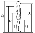 The first rule of design for any workstation is that the controls comply with anthropometric data on human operators. For example, controls must be within a comfortable reach of 5th percentile women and 95th percentile men and should not require awkward positions or inordinate muscle strength. You will find data on population anthropometrics and reach envelopes in the Workstation Layout section of this web page.
Another important human factors principle is that controls should be in optimum positions based on criticality, frequency of use, and sequential links. Criticality in this context refers primarily to safety. At each workstation, the panic bar should receive priority in location. Most frequently used controls should be in the most convenient locations; less frequently used controls may be in less optimum positions. Controls should be located relative to each other based on sequential links between the controls. An optimum configuration is a compromise of the three principles above. Relative importance of each principle depends on the function of that control group.
In addition, such things as fatigue and minimum clearances should also be considered. For example, requiring the roof bolter operator to pull up on a feed control while drilling would cause undue fatigue. You should also ensure that there is enough clearance between controls for gloved-hand operation.
Combining control functions into one control can improve efficiency. Combining functions decreases hand motions between controls and reduces control clutter. For example, a roof bolter can have one control that is pushed for rotating and pulled for torque. Such a design reduces hand motion, decreases the incidence of over torque bolts, and increases efficiency.
Identification
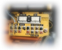
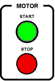
 The ability to quickly identify a control can be crucial in avoiding accidents when working in the underground mine environment. Control identification is done through various methods of control coding. The most important types of control coding for underground mining machinery are labeling, size, shape, location, and color. (The example on the right has obvious problems with identification, including no labeling, no shape or size coding, and controls that are too tightly spaced.)
Many underground mobile mining machines have several major types within a class of equipment. For instance, roof bolters can be single- or dual-boomed, with or without an Automated Temporary Roof Support (ATRS). Controls within each of these types should be very similar. Also, when possible, controls between different classes of equipment (shuttle cars, scoops, continuous miners, etc.) should be similar.
Labeling and Standard Terminology
Controls should have appropriate labels, showing the function controlled and method of operation, to ease rapid, accurate, and safe operator performance. However, if the method of operation is obvious (e.g., an automotive-type steering wheel), labeling is not necessary.
- Labels should be located systematically in relation to the controls (e.g., always above or always below).
- Labels should tell what they are controlling (e.g., conveyor boom or fast feed).
- Use terminology or symbols that are familiar to all operators.
- Label style should be consistent across machines and readable under all working conditions. The design of letters and numerals should be a plain, simple block type.
 For a 28-in (71.12-cm) viewing distance with a brightness level of 1 fL (.2919 nt) (the height of characters used for labeling equipment functions should be from 0.20 to 0.30 in (.51 to .76 cm). The height of characters on labels that describe the control method of operation should be 25% smaller than those used to identify equipment functions. The width of characters should be approximately three-fifths of the height (as in the example on the right). Note: The MSHA Illumination Standards for coal mines requires the brightness in the normal working places of underground coal mines to be not less than 0.06 fL (.02 nt).
- Labels should be visible while the operator is using the control. Mount labels to reduce wear and obscurement by grease and dirt. Construct them of materials that permit easy cleaning with readily available cleaning solutions (water, hydraulic oil, etc.).
- Where dark adaptation is required or ambient illumination is less than 1.0 fc (.0929 lx), use white phosphorescent characters on a dark (black) background.
- Label a control that fulfills the same function on different machines with the same name. Develop standard terminology for each control. Standard terminology and labeling also helps maintenance personnel in hooking up controls, valves, and hoses correctly after repair.
Code by Size
At each workstation, the primary controls should be longer or larger than the others. This immediately designates them as the primary controls and reduces the number of incorrect actuations of subordinate controls.
Code by Control Shape or Type
The shape or type of control should immediately tell an operator its general function. For instance, levers should be reserved for the control of machine component motion. To use a lever to control a hydraulic diversion valve not related to machine motion may confuse an operator. Diversion valves, such as the one that controls the drill/torque function on roof bolters, should be a non-lever control (possibly a push-pull knob) to prevent confusion with component movement controls. (Show me examples of shape coding.)
Code by Location
Group controls doing similar or related functions together. This helps the operator tell at a glance which controls relate to which functions. Functional groups of controls should be as near as possible in the same location on machines of the same type and in the same location across classes of machines. Controls for unrelated functions requiring simultaneous operation should be separated so that the left hand controls one function and the right hand controls the other.
Once a group of controls is designated as a functional group, standardize their locations within that group relative to each other. Once an operator learns that rotate is to the left of feed, he or she should not have to relearn that rotate is to the right of feed on the right boom. The original reason for placing controls in a mirror image on either side of the machine was to place the most important control nearest the chuck. However, if all primary drilling controls are within easy reach of the chuck, this argument has little validity. Do not use mirror-image controls since they may confuse the operator and do not increase efficiency.
Color
Coding of control knobs for color recognition requires sufficient illumination to be useful. Because of the problems of low illumination, general wear or abuse, and soiling of control knobs with use, the only color coding recommended is limited to emergency equipment. Therefore, emergency equipment, including the emergency OFF controls (panic bars) and fire control equipment, should be color-coded red.
Control Response Relationships
Operators learn faster and make fewer errors when they move a machine component in the same direction as the lever that controls it. For example, the machine should move forward when the tram lever is moved forward, not sideways, up, or down. A stabilizer jack control lever should move upward to raise the vehicle, and downward to lower it. Distinguishing between a motion direction that is only a part of accomplishing a function, and the actual motion direction of the function, is important. The control designer should not think, "Lower the stabilizer jack control lever to lower the jack to raise the vehicle," but should instead think, "Raise the lever to raise the vehicle," and design the control accordingly. It has also been found that employers can teach operators to operate the control in another direction, but in a panic situation they generally move the control in the desired direction of component movement instead of the direction taught. Consequently, one of the most important control optimizations is to have the control move in the direction of the component controlled.
One caveat exists to the above principle. Some control movements do not comply exactly with human engineering principles, but have become standard practice within the industry. Do not change them unless substantial benefits are involved. For example, the logical movement for the roof bolter feed control is up for feed and down for lower. However, this design would require the operator to spend most of the time holding the feed control up, leading to potential fatigue problems. Since anthropometric considerations prevent modifying control movement to the optimum direction, it should agree with most feed controls (in for feed). The roof bolter rotate control is also well standardized across most machines (in for clockwise). Its motion should agree with the feed control since they are used together.
| Control Type | Recommended Control Motions |
|---|---|
| Foot pedals |
Push to: activate, accelerate forward, apply brakes, activate retarders, turn on/off, engage a function Release to: deactivate, decelerate, release, disengage |
| Levers |
Push forward to: stop, move backwards, engage brakes, raise Pull backwards to: stop, move backwards, engage brakes, raise |
| Push buttons | Push to: engage/disengage |
| Rotary switches | Turn clockwise to: increase speed/volume |
| Toggle switches |
Push up to: Select a function, activate Push down to: deactivate |
| Emergency cutoff buttons and switches | Push to: deactivate |
| Cranks and wheels | Turn right to: start, increase speed, turn to right |
Another human factors principle is that a control should move toward the component activated. For example, a control that diverts power from one component to another (for example, a drill/tram lever) should move toward the chuck for drilling and the cab for tramming.
Where feasible, design the hydraulic valves and linkages attached to levers that control variable functions so the rate of vehicle or component movement is proportional to displacement of the control from its "rest" or position.
Resistance
You must always apply some force to move a control. The main types of resistance they can have are listed below:
| Type | Description |
|---|---|
| Elastic | Spring loaded-the greater the displacement of a control, the greater the resistance. |
| Static | Resistance to initial movement is maximum, but drops off sharply as a control is moved (sticky). |
| Coulomb | Continued resistance to movement that is unrelated to the velocity or displacement of a control movement. Resists change in direction. |
| Viscous damping | Like moving a spoon through thick syrup. The faster one moves a control, the more resistance is encountered. Resists quick changes in direction and helps execute smooth control movements |
| Inertia | Resistance to movement or change in direction caused by the mass of the mechanism. Resists quick control movements and any attempt to slow or speed up control movements. |
A little elastic resistance is usually desirable, but inertial resistance often causes a decline in control precision. (2) Nearly all controls have mass and therefore inertia. Most controls move on a slide or around a shaft or pivot and, therefore, have sliding friction. In addition, there are interactions between the various kinds of resistance and operator performance. Viscous damping, for example, can sometimes be helpful in counteracting the adverse effects of inertia or vibration.
Depending on the kind and amount, resistance can affect the following:
- The precision and speed of control operation.
- The "feel" of the control.
- The smoothness of control movement.
- The susceptibility of the control to accidental activation, to the effects of vibration and G forces, etc.
The designer should build into the control the kind or kinds of resistance that best satisfies performance requirements. Usually, resistance for hand controls (except finger-operated controls) should not be less than 2 lb (.91 kg). Below 5 lb (2.27 kg), the pressure sensitivity of the hands is poor, reducing touch feedback associated with control actuation. If the arm and hand are used on a control, the minimum resistance should be 10 to 12 lb (4.54 to 5.44 kg); if only the forearm and hand, 5 lb (2.27 kg); if only the hand, 2 lb (.91 kg). (3) Limits of the resistance of hand controls are difficult to determine because of wide variations in the operator population, types and locations of controls, and the frequency, duration, direction, and amount of control movement. For example, there is more than a fourfold difference in the push that can be exerted on a control stick depending on whether it is on the midline of the body away from the operator (maximum) or to the left of a right-handed operator (minimum). In spite of this, there are some recommendations for maximum control resistance; they are found in the sections on individual control types.
Any component movement has a potential for injury. This movement must be under complete control of the operator and requires his or her continued attention. The most effective method for ensuring this attention is to use self-centering controls without detents.
Dead space in a control mechanism is how much control movement around the null position results in no response of the device being controlled. A little dead space is usually desirable, especially if vibration and buffeting of an operator are present. Too much dead space, however, can be detrimental to operator performance. (2)
Preventing Accidental Activation
Standard methods of protecting controls against inadvertent activation include: (3)
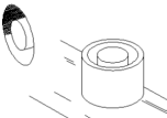 Recessing - Recess controls so that they do not protrude above the control panel surface. Another technique is to place raised barriers around the control. A disadvantage of this method is that it may require more panel space. (In the examples on the right, one button is recessed into the control panel. The other has a guard around it, which effectively recesses the control.)
- Location - Locate controls so that the operator cannot hit them accidentally. Isolating one control from others can accomplish this. Or arrange controls so that the sequence of operations is not conducive to accidental activation.
- Orientation - You can orient the direction of movement of the control along an axis in which accidental forces are least likely to occur however, take care should to ensure that you do not violate recommended direction-of-motion relationships.
- Covering - Protective covers or guards can be placed over the control. If operators use the control frequently, however, they will probably disable the guards.
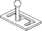 Locking - Controls can be locked in position (see the example on the right, which can be locked into 3 positions). This method generally requires the sequential application of force in at least two directions to release and operate the control. Like covering, this method is undesirable if the control is used frequently.
- Operation Sequencing - A series of interlocks can prevent Step 2 from being performed before Step 1. One example would be a boom raise control that operators cannot use unless they have already activated a foot operated dead man control.
- Resistance - Use of the proper kind or kinds and amount of resistance prevents accidental forces from activating the control.
It is also good practice to key components (by size or shape of coupler) so that maintenance personnel cannot install them in the wrong location. It does no good to standardize controls if maintenance personnel switch hoses into the wrong valves.
Design Principles for Mining Control Types
The following sections detail some design principles for hand cranks, hand wheel, levers, push buttons and pedals.
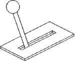
Hand Cranks
 Hand Cranks are used for making adjustments when large distances must be covered and high rates of turning are needed. Because multiple rotations are generally used when operating a hand crank, the position of the hand crank does not usually indicate the control setting. Use properly geared hand cranks for gross or fine positioning. A common use for a hand crank is to operate a manual pump.
| RPM | Handle Length in (cm) |
Handle Diameter in (cm) |
Max. Radius in (cm) |
Min. Radius in (cm) |
Max. Resistance lb (kg) |
Min. Resistance lb (kg) |
|---|---|---|---|---|---|---|
| 0-175 | 3.75 (9.53) |
1.00 (2.54) |
16.00 (40.64) |
9.00 (22.86) |
50.00 (22.68) |
2.00 (.91) |
| 175-275 | 3.75 (9.53) |
1.00 (2.54) |
8.00 (20.32) |
5.00 (12.7) |
80.00 (36.29) |
15.00 (6.80) |
| 275 and up | 1.60 (4.06) |
0.50 (1.27) |
4.50 (11.43) |
0.50 (1.27) |
5.00 (2.27) |
2.00 (.91) |
Hand Wheels
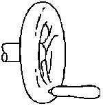
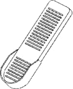
Use hand wheels for two-handed operation. They are useful for exerting greater rotary force than is possible with knobs or cranks. They generally require a large amount of space for installation and operation. A common use for a hand wheel is to control steering.
Provide molded rims on the hand wheel to aid in grasping it. Provide the surface of the rim of the hand wheel with high frictional resistance. When the hand wheel is to be turned less than 120 degrees, only the two sections of the hand wheel that the operator grasps need to be provided. These parts are usually the chords of arcs, approximately 6 in (15.24 cm) long, across from one another. This technique can increase operator visibility and result in more space for pedal operation.

Hand wheel examples
| Value | Wheel Diameter in (cm) |
Resistance lb (kg) |
|---|---|---|
| Minimum | 2.00 (5.08) |
5.00 (2.27) |
| Maximum | 4.25 (10.80) |
30.00 (13.61) |
| Value | Wheel Diameter in (cm) |
Resistance lb (kg) |
|---|---|---|
| Minimum | 7.00 (17.78) |
5.00 (2.27) |
| Maximum | 21.00 (53.34) |
50.00 (22.68) |
Levers
 Levers are preferred for the control of component movement. They give the operator feedback about the control position and resistance, improving their feel concerning the component controlled. Common uses for levers include raising the drill head or swinging a conveyor boom.
Provide support for the body part being used if a lever is for making fine adjustments, e.g., elbow support for large hand movements, forearm support for small hand movements, and wrist support for finger movements. If making very fine adjustments with a small joystick (such as for a remote control for a continuous miner), operators may rest their wrists on the control panel and grasp the control pencil-style below the tip rather than on it. For such situations, recess the pivot point below the surface on which the wrist rests.
Levers for component movement should be self-centering - the lever should return to its null position when force is removed. Provide the surface of the handle of a lever with a high degree of frictional resistance to prevent slipping.
| Value | Seat Back 90 to 60 Degrees | Seat Back 60 to 0 Degrees |
|---|---|---|
| Maximum Lateral in (cm) |
38.00 (96.52) |
14.00 (35.56) |
| Maximum Fore-Aft in (cm) |
14.00 (35.56) |
7.00 (17.78) |
| Value | Seat Back 90 to 60 Degrees | Seat Back 60 to 0 Degrees |
|---|---|---|
| Maximum in (cm) |
36.00 (91.44) |
18.00 (45.72) |
| Minimum in (cm) |
24.00 (60.96) |
12.00 (30.48) |
| Value | Seat Back 90 to 45 Degrees | Seat Back 45 Degrees |
|---|---|---|
| Minimum lb (kg) |
5.00 (2.27) |
2.50 (1.13) |
| Maximum lb (kg) |
50.00 (22.68) |
25.00 (11.34) |
| Preferred lb (kg) |
25.00 (11.34) |
10.00 (4.54) |
| Value | Diameter in (cm) |
Length in (cm) |
|---|---|---|
| Minimum | 0.75 (1.91) |
3.70 (9.40) |
| Maximum | 1.50 (3.81) |
No Maximum |
| Value | Resistance lb (kg) |
|---|---|
| Minimum | 2.00 (.91) |
| Maximum | 30.00 (13.61) |
Push Buttons
 Design push buttons to be operated by the fingers, thumb, or the palm or heel of the hand. Resistance (elastic) should start low, build rapidly, then drop suddenly to indicate that the control has been activated. The surface of the push button should have a high degree of frictional resistance to prevent slipping. Push buttons should be used with displays in dimly lighted areas that indicate that the control has been activated and show the position of the control.
| Value | Diameter Finger-Operated in (cm) |
Diameter Thumb/Palm-Operated in (cm) |
Resistance oz (kg) |
|---|---|---|---|
| Minimum | .5 (1.27) |
.75 (1.91) |
10 (.28) |
| Maximum | No Maximum | No Maximum | 40 (1.13) |
Pedals
 Because operators cannot usually see pedals, they are harder to identify. Pedals are coded only by location. Using the appropriate resistance can prevent their accidental activation. The pedal should return to its null position when force is removed.
Do not use pedals when the operator is standing on a moving vehicle. If you recline the seated operator more than 60 degrees, pedals should not be used for accelerators or brakes.
The shape (rectangular, round, oval, etc.) and size of the pedal can vary if it is flat and provides a large enough area of contact with the shoe. Most pedals should be as wide at the sole of the shoe. Pedals used continuously or for long periods should be at least 11 in (27.94 cm) long. Those used intermittently should be at least 3 in (7.62 cm) long.
Use a pedal bar or recessed heel section to keep the foot from slipping off the pedal. They can also help the operator in finding the pedal by feel. This is helpful when the operator must wear heavy boots.
| Pedal Use | Minimum in (cm) |
Maximum in (cm) |
|---|---|---|
| One Foot, Random | 4 (10.16) |
6 (15.24) |
| One Foot, Sequential | 2 (5.08) |
4 (10.16) |
| Seat Back | Pedal Angle (Degrees) |
|---|---|
| Normal | 75 to 90 |
| Reclined | 45 to 60 |
| Supine | 30 to 45 |
| Configuration | Minimum lb (kg) |
Maximum lb (kg) |
|---|---|---|
| Foot Not Resting on Pedal | 4.00 (1.18) |
20.00 (9.07) |
| Foot Resting on Pedal | 10.00 (4.54) |
20.00 (9.07) |
| Ankle Flexion Only to Activate | No Minimum | 10.00 (4.54) |
| Total Leg Movement Required to Activate | 10.00 (4.54) |
180.00 (81.65) |
| Configuration | Minimum lb (kg) |
Maximum lb (kg) |
|---|---|---|
| Foot Not Resting on Pedal | 4.00 (1.18) |
20.00 (9.07) |
| Foot Resting on Pedal | 4.00 (1.18) |
20.00 (9.07) |
| Ankle Flexion Only to Activate | 4.00 (1.18) |
10.00 (4.54) |
| Total Leg Movement Required to Activate | 10.00 (4.54) |
90.00 (40.82) |
References
- Sanders, M. S., and J. M. Peay. Human Factors in Mining. USBM IC 9182, 1988, 153 pp.
- Joint Army-Navy-Air Force Steering Committee. Human Engineering Guide to Equipment Design. John Wiley and Sons, 1972, 752 pp.
- Gilbert, V. A. Research Support for the Development of SAE Guidelines for Underground Operator Compartments (contract H0308110, Society of Automotive Engineers, Land & Sea Division). USBM OFR 8-91, 1990, 211 pp.; NTIS PB 91-146142.
- Applied Science Associates, Inc. Standardization of Controls for Underground Electric Face Equipment - Phase I (contract H0230021). USBM OFR 15-74, 1973, 105 pp.
- A Checklist for Evaluating Cab Design of Construction Equipment
- Ergonomic and Existing Seat Designs Compared on Underground Mine Haulage Vehicles
- Experiments on Personal Equipment for Low Seam Coal Miners: IV. Incorporating Coiled Cord Into Cap Lamp Battery Cords
- Inexpensive, Easy to Construct Materials-handling Devices for Underground Mines
- Job Design: An Effective Strategy for Reducing Back Injuries
- Laboratory Investigation of Seat Suspension Design Performance during Vibration Testing
- Seating Design Principles
- Self-Reported Musculoskeletal Symptoms Among Operators of Heavy Construction Equipment
- Systematic Comparison of Different Seats on Shuttle Cars Used in Underground Coal Mines
- Task Analysis
- Transverse-Mounted End-Cab Design for Low-Coal Shuttle Cars
- Underground Workstation Design Principles