
City Maintenance Worker Dies After Being Pinned In Street Sweeper
MN FACE Investigation 02MN034
Date: February 26, 2003
SUMMARY
A 43-year-old city employee (victim) died after he was pinned between the hopper and the suction hose of a street sweeper. The sweeper design, known as a cross wind design uses a loop of air which results in less dust being returned to the environment. A large flexible suction hose connects one end of the sweeper’s pickup head to the collection hopper.
All of the sweeper’s operating controls are located in the cab of the sweeper except for the controls to empty the collection hopper. The hopper controls consist of two levers that are located on the right hand side of the unit. They are recessed beneath the collection hopper and are directly under a steel plate designed to prevent the levers from being inadvertently activated. A safety/warning sign on the top of the plate reads “NO STEP”. When the lever to raise the hopper is pulled up, the hopper raises and debris is dumped from the hopper. When the lever is pushed down, the hopper lowers to it’s down position.
The sweeper was equipped with a hopper support (safety) bar to prevent the hopper from lowering during maintenance and repair. The safety bar can be put in use when the hopper is raised by pulling the head of a small pin from a rubber grommet to release the bar. The lower end of the bar then rests in a steel holder from which it must be manually lifted before the hopper can be lowered. At the time of the incident, the safety bar was not in use.
The victim and other city workers worked on the east side of the city until 10:20 a.m. when they stopped for a break. After the break, the victim drove the sweeper to a landfill to empty the collection hopper. He backed the sweeper into a dumping area at the landfill, got out of the cab and emptied the hopper.
After dumping the hopper, the victim apparently used a steel bar to dislodge items from the unit’s suction hose. Apparently, after tapping on the hose, he climbed up to look down into it. While looking into the suction hose, he may have placed his right foot on a safety plate located above the hopper control levers. While in this position, his foot apparently slipped and struck the lever that raised and lowered the hopper. The hopper lowered and the victim became pinned between the top of the suction hose and the side of the hopper.
At approximately 12:15 p.m., another worker arrived at the landfill with a dump truck loaded with debris. He noticed the sweeper in the same position that he had previously seen it earlier that day. He drove his truck over to the sweeper to determine if there was a problem and found the victim. He used a two-way radio to call for help. Two other city employees who were at the landfill were also notified by the truck driver and rushed to the scene. They raised the hopper and freed the victim. A coroner and other emergency personnel arrived at the scene shortly after the victim was freed. The coroner examined the victim and pronounced him dead at the scene.
The sweeper was examined several days after the incident. It was found that all of its mechanical and hydraulic systems were in working condition and that the incident was not the result of any type of equipment or system failure. MN FACE investigators concluded that to reduce the likelihood of similar occurrences, the following guidelines should be followed:
- workers should always use all safety devices that machines are equipped with to prevent injury and exposure to hazards,
- equipment manufacturers should incorporate passive safety devices and systems in the design of machines to protect workers from unexpected movement of components; and
- when considering human factors, manufacturers should locate operating controls so as to provide the maximum possible protection against inadvertent and unexpected movement of machine components.
INTRODUCTION
On September 18, 2002, the MN FACE program was notified of a work-related fatality that occurred on September 3, 2002. On October 31, 2002 a site investigation was conducted by a MN FACE investigator. During the site investigation, the employee services director for the city provided detailed information and photographs of the equipment associated with this incident. During MN FACE investigations, incident information is obtained from a variety of sources such as Minnesota OSHA, law enforcement agencies, county coroners and medical examiners, employers, coworkers and family members.
The victim was a Maintenance (I) employee for a city with a population of approximately 16,000. He had been employed by the city since December 19, 1983. During his employment his general duties and responsibilities included tasks associated with street maintenance, concrete projects, snow plowing and street sweeping. On April 22, 2002, he was assigned to work full time as a sweeper operator due to a lower back injury on February 11, 2001 that limited his lifting ability.
The employer has a written safety program that includes both formal and hands on training. The victim had attended a documented one day Elgin Sweeper Clinic on March 21, 2002 with two other city employees. The victim received hands on operator and safety training for the sweeper from the Operations Foreman. This training included oral instructions to use the hopper safety bar when inspecting, cleaning or doing maintenance on the unit however this training was not documented. Since the time of the incident and subsequent investigations, the employer has increased the training requirements for sweeper operators and mechanics. All operators and mechanics must complete Job Safety Analysis (JSA) training, read the operators manual, receive training from a qualified vendor or operator and complete a hands on demonstration of the operational functions of the unit to a trainer.
INVESTIGATION
The victim reported to work at 7:00 a.m. on the Tuesday following the three day Labor Day weekend. Over the weekend a wind and rain storm had passed through the area. Some of the city’s streets were littered with debris such as small twigs, sticks, leaves, etc. which required that they be swept. The victim got into a street sweeper and drove it to the east side of the city where he and other city workers began cleaning the streets.
The sweeper that the victim was operating was purchased new by the city in 2000. The sweeper was an Elgin Series J Crosswind Sweeper (Figure 1). The crosswind design uses a device called an impeller to move air through the sweeper in a continuous loop. The air is blown down a pressure hose on the left side of the unit, through a pressure slot and into the sweeper’s pickup head. This creates turbulence as the air flows across the pickup head and lifts debris from the street. Air and debris are pulled from the right side/end of the pickup head through a large suction hose. The air and debris then enter a collection hopper and are spun around in the hopper to separate the debris from the stream of air. The air stream then reenters the impeller and is forced back down the pressure hose. Re-circulation of the air instead of venting it to the outside results in less dust being returned to the environment.
The sweeper’s pickup head is 90 inches long, extends across the width of the sweeper and is located in front of the unit’s rear wheels. A twelve inch diameter flexible suction hose connects one end of the pickup head to the sweeper’s collection hopper. The suction hose is about 5 feet long and extends vertically from the end of the pickup head in front of the right rear wheels to a round opening in the bottom of the hopper (Figure 2). When the hopper is in the lowered position, the hopper contacts the discharge end of the suction hose and forms a seal for the transfer of debris from the pickup head to the collection hopper. When the hopper is raised to empty the sweeper, the seal between the discharge end of the suction hose and the hopper is broken as the hopper is raised.
All of the sweeper’s operating controls are located in the cab of the sweeper except for the controls to empty the collection hopper. The controls for dumping the hopper (Figures 3a and 3b) consist of two levers that are located on the right hand side of the unit. The levers are located approximately 20-24 inches in front of the right rear wheels and about 30 inches above ground level. The levers are recessed slightly beneath the collection hopper and are also directly under a steel safety plate designed to prevent the levers from being inadvertently activated. A safety/warning sign on the top of the plate reads “NO STEP”. While facing the control levers, the left lever operates the hopper door and the right lever controls the raising and lowering of the collection hopper. When the door lever is pulled up, the hopper door opens and when it is pushed down the door closes. When the hopper lever is pulled up, the hopper raises and debris is dumped from the hopper. When the hopper lever is pushed down, the hopper lowers to its down or operational position.
When the hopper is raised to it’s maximum height, there is a space or opening between the right side of the sweeper hopper and the top of the suction hose (Figures 4a and 4b). This space/opening is approximately 14-16 inches wide and provides enough room for an operator to climb up and look into the large suction hose.
The sweeper is equipped with a hopper support (safety) bar (Figure 5) that can be used to prevent the hopper from lowering during maintenance and repair activities. One end of the support bar is attached to a pivot point on the underside of the hopper. The support bar is kept in a stowed position by a small tapered pin with an enlarged head welded to the top side of the bar. The enlarged head of the pin is pushed through a rubber grommet inserted in the frame of the hopper when the bar is not being used. The safety bar can be put in use when the hopper is raised by pulling the head of the small pin from the rubber grommet to release the bar. The lower end of the bar then rests in a steel holder from which it must be manually lifted by the operator before the hopper can be lowered.
The victim and other city workers were working on the east side of the city until 10:20 a.m. when they stopped for a rest break. Shortly after the break, the victim drove the sweeper to a nearby landfill to empty the collection hopper. He backed the sweeper into a dumping area at the landfill and got out of the cab, apparently via the right side door that was open when the victim was found. The victim opened the hopper door and raised the collection hopper by pulling up on the two control levers on the side of the unit.
After dumping the debris from the hopper, the victim apparently used a 1 inch diameter by 12 inch long steel bar to dislodge stuck items from the vertical suction hose. This was routinely accomplished by tapping the suction hose with the steel bar. The bar, which workers had put in the cab of the sweeper was found on the ground near the sweeper’s right rear wheels. Apparently, after tapping on the hose, the victim climbed up to look down into the suction hose to ensure that it was clear of debris. While looking into the suction hose, the victim may have placed his right foot on the safety plate located directly above the two hopper control levers. While in this position, his foot apparently slipped and struck the lever that controlled the raising and lowering of the hopper. When the lever was inadvertently pushed down, the hopper began to lower. Because of the small distance between the victim and the bottom of the hopper, he became pinned between the top of the suction hose and the side of the hopper.
At approximately 12:15 p.m., another city worker arrived at the landfill with a dump truck loaded with storm debris. He noticed the sweeper in the same position that he had previously seen it while dumping another load of debris earlier that day. He drove his truck over to the sweeper to determine if the victim was having a problem and in need of assistance. He walked around to the right side of the sweeper and found the victim pinned between the hopper and the top of the suction hose.
The truck driver used a two way radio in his truck to call for help and then returned to the victim. The driver was not familiar with the operation of the sweeper and was not able to immediately free the victim. Two other city employees who were at the landfill were notified of the situation by the truck driver and rushed to the scene. They managed to raise the hopper and free the victim who fell to the ground. They checked the victim for vital signs but it was apparent to them that the victim was deceased. A coroner along with other emergency personnel arrived at the scene shortly after the victim was freed. The coroner examined the victim and pronounced him dead at the scene.
The sweeper was thoroughly examined by employees of the city several days after the incident. It was determined that all of the sweepers mechanical and hydraulic systems were in proper working condition at the time of the incident and that this incident was not the result of any type of equipment or system failure.
CAUSE OF DEATH
The cause of death listed on the death certificate was blunt force head and neck injuries with suspension due to street sweeper truck mishap.
RECOMMENDATIONS/DISCUSSIONS
Recommendation #1: Workers should always use all safety devices that machines are equipped with to prevent injury and exposure to hazards.
Discussion: Modern machines such as the sweeper associated with this incident are designed and equipped with a variety of effective safety devices. These devices protect workers while the machines are being used and during maintenance and repair of the machines. Safety devices are designed to prevent workers from being exposed to hazards and hazardous situations or to eliminate hazards in certain cases. In this incident, the sweeper was equipped with a hopper support (safety) bar that when used, prevents the hopper from lowering to its operational position. The safety bar could be put in place when the hopper was raised by pulling the head of the small retaining pin from the rubber grommet to release the bar. The lower end of the bar then rests in a steel holder from which it must be manually lifted by an operator before the hopper can be lowered. Use of the safety bar will prevent the hopper from being lowered inadvertently or lowering due to a failure of a component of the hydraulic system that raises the hopper. Before checking the suction hose for debris the victim did not lower the safety bar to keep the hopper in its raised position. In this case, if the safety bar had been used this fatality probably would have been prevented.
Recommendation #2: Equipment manufacturers should incorporate passive safety devices and systems in the design of machines to protect workers from unexpected movement of components.
Discussion: Advances in safety engineering, design and product development have resulted in safer machines equipped with passive as opposed to active safety devices. An active safety device or system requires an operator to perform a specific and deliberate action “to use or to put in use” the safety device or system. Passive safety systems, such as retractable saw blade guards that expose the blade when the saw is used for cutting and then automatically cover the blade when the saw is returned to it’s “not in use” position, require no action on the part of the operator.
The hopper safety bar that the sweeper is equipped with is an active safety device requiring the operator to put it in use. The safety bar could be redesigned as a passive safety device such that as the hopper was raised, the safety bar would automatically drop into one of several locking positions. This would automatically lock the hopper in a raised position and prevent it from lowering onto a worker who even briefly enters the area under the raised hopper. A passive safety bar would need to be designed with an active release mechanism that would allow the operator to disengage the bar from its locked position “prior to and while” the hopper is lowered to its operational position. In addition, the safety bar release would need to be designed such that it would not be possible for workers to bypass or override the locking or the unlocking mechanism, thereby rendering the safety bar ineffective. If the sweeper’s safety bar had been designed as a passive safety system, this fatality might have been prevented.
Recommendation #3: When considering human factors, manufacturers should locate operating controls so as to provide the maximum possible protection against inadvertent and unexpected movement of machine components.
Discussion: The hopper controls of the street sweeper were located immediately adjacent to the suction hose and covered by a steel plate intended to protect the controls against inadvertent activation. The cover was marked with a “no step” warning placard. Although not intended as an access step, the location of the cover was such that it afforded ready access to the top of the suction hose if used as a step. Locating the controls away from the suction hose, further forward and near the truck cab, for example could decrease the potential for workers to use the protective cover as a step. Additionally, the steel plate could be extended to more effectively cover the controls and a separate step could be located to provide access to the suction hose.

Figure 1. Elgin Series J Crosswind Sweeper at the incident site.

Figure 2. 12″ diameter suction hose with hopper raised to dump debris.
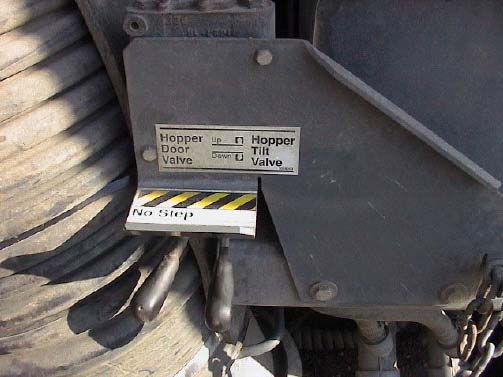
Figure 3a. Hopper control levers and “No Step” warning on top of safety plate.
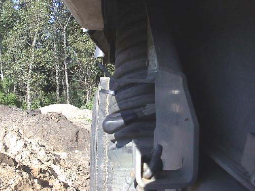
Figure 3b. End view of hopper levers and safety plate – NOTE: plate extends to ends of levers.

Figure 4a. Sweeper with hopper raised showing space between side of hopper and top of suction hose.

Figure 4b. Close up of space between side of hopper and top of suction hose.
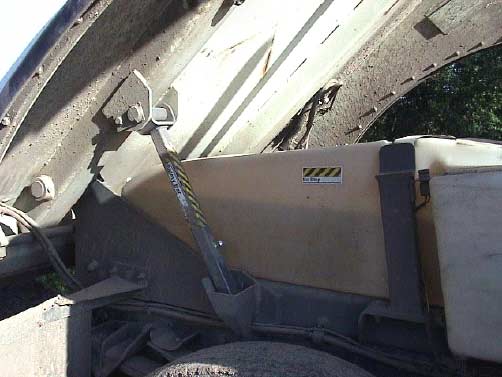
Figure 5. Hopper support safety bar in “In Use” position.
To contact Minnesota State FACE program personnel regarding State-based FACE reports, please use information listed on the Contact Sheet on the NIOSH FACE web site. Please contact In-house FACE program personnel regarding In-house FACE reports and to gain assistance when State-FACE program personnel cannot be reached.