Underground Workstation Design Principles
Introduction
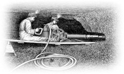
Machine designers call any location on a mining machine where one or more operators routinely control machine functions a workstation. Some types of mining machines, such as roof bolters, can have multiple workstations.
The environment poses many challenges for the designers of underground mobile mining equipment. Foremost are the practical limits on the size of the workstation itself and the operator's position within it. Because lower-seam mines have insufficient vertical height to permit an erect seated operator position, the operator is forced to assume various reclined positions. More fully reclined positions demand careful placement of hand and foot controls for operators in this disadvantaged position.
If the workstation does not have a seat, the design may require that the operator stoop, kneel, or crouch to operate the machine. Again, the designer must pay attention to the design and placement of controls to ensure safe, efficient machine operation. If the workstation has a canopy, the designer must make additional allowances for operator visibility and head clearance while wearing a hard hat. Finally, the dimensions of the workstation must be sufficient to permit free arm-to-control movements and operator ingress-egress.
If you follow the first principles for workstation design for underground mobile mining equipment, you will address most of the challenges listed above:
 Anthropometrics - Use anthropometric data from within the 5th- to 95th-percentile range. Consider the limits imposed by operators with shorter arms when identifying the arm reach envelope for the location of controls. For clearance requirements for the head, knees, etc., use data from the larger members of the user population. For visual accommodation, ensure that the entire potential range of eye positions is taken into account.
 Work Design - Where practical, distribute the workload as evenly as possible between hands and feet. Primary controls requiring precision operation should be positioned for use by either hand. If that is not possible, give preference to the right hand. Emergency controls should be equally available to both hands.
 Operator Protection - Anticipate all potential safety hazards and required emergency actions before starting to design.
 Standardization - Maintain the relative placement of controls and displays for similar types of equipment. This takes advantage of established habits and helps to eliminate unnecessary retraining.
Priorities in Workstation Design
Designers have many competing priorities that must be reconciled when laying out a workstation. This is especially true when you try to develop a workstation for use in the restricted space of the underground environment. The following are some recommended priorities for laying out an underground workstation: (2)
- Priority 1 - Consider the primary visual tasks. Whether it is to look at the roadway ahead or to monitor a display device, the eye position relative to the task establishes the basic layout.
- Priority 2 - Determine the placement of primary controls associated with a primary visual task (e.g., a steering wheel). Emergency controls are also primary items. Because primary and emergency control positions are generally related to a seat reference point, this is an appropriate time to identify that location.
- Priority 3 - Consider the control/display relationships. Controls should be near the displays they affect and should have a direction of movement that corresponds to the direction of movement of the display that the control affects. The act of activating the control should not obscure the display.
- Priority 4 - Arrange the workstation elements in their anticipated sequence of operation (usually from left to right and top to bottom).
- Priority 5 - Place the workstation elements according to frequency of use.
Workstation Design Guidelines
The following sections provide basic information related to workstation design. Each section corresponds to one of the previously mentioned first principles of workstation design for mobile underground mining machinery. (1, 2, 3)
Anthropometrics
Of the hundreds of anthropometric measurements possible from the human body, the 21 listed below are all you will need to lay out the vast majority of underground workstations. The data are for the 5th-percentile female and the 95th-percentile male. The subjects are lightly clothed with no hard hat, battery pack, self-rescue device, or hand tools hanging from the belt. Therefore, these values represent the minimum dimensions for each size category.

| A Prone Height | 18.9 in (46.5 cm) |
|---|---|
| B Prone Length | 107.9 in (274.1 cm) |
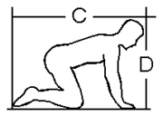
| C Kneeling Length | 55.5 in (140.0 cm) |
|---|---|
| D Kneeling Height | 39.4 in (100.1 cm) |
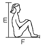
| Anthropometric | Men | Women |
|---|---|---|
| E | 38.3 in (97.3 cm) | 33.6 in (85.3 cm) |
| F | 35.4 in (89.9 cm) | 34.5 in (87.6 cm) |

| Anthropometric | Men 5th | Men 50th | Men 95th | Women 5th | Women 50th | Women 95th |
|---|---|---|---|---|---|---|
| G Shoulder Breadth | 16.5 in (41.9 cm) | 18.2 in (46.2 cm) | 19.8 in (50.3 cm) | 14.7 in (37.3 cm) | 16.5 in (41.9 cm) | 18.3 in (46.5 cm) |
| H Hip Breadth | 12.6 in (32.0 cm) | 14.2 in (36.1 cm) | 15.7 in (39.9 cm) | 12.6 in (32.0 cm) | 14.8 in (37.6 cm) | 17.1 in (43.4 cm) |
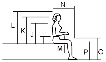
| Anthropometric | Men 5th | Men 50th | Men 95th | Women 5th | Women 50th | Women 95th |
|---|---|---|---|---|---|---|
| I Elbow Rest Height | 7.7 in (19.6 cm) | 9.4 in (23.9 cm) | 11.2 in (28.4 cm) | 7.4 in (18.8 cm) | 9.4 in (23.9 cm) | 10.6 in (26.9 cm) |
| J Shoulder Height | 21.6 in (54.9 cm) | 23.8 in (60.5 cm) | 25.9 in (65.8 cm) | 20.3 in (51.6 cm) | 22.4 in (56.9 cm) | 24.6 in (62.5 cm) |
| K Eye Height | 29.3 in (74.4 cm) | 31.7 in (80.5 cm) | 38.0 in (96.5 cm) | 27.2 in (69.1 cm) | 29.4 in (74.7 cm) | 31.5 in (80.0 cm) |
| L Sitting Height | 33.7 in (85.6 cm) | 36.0 in (91.4 cm) | 38.3 in (97.3 cm) | 31.3 in (79.5 cm) | 33.6 in (85.3 cm) | 35.9 in (91.2 cm) |
| M Thigh Clearance | 5.0 in (12.7 cm) | 6.0 in (15.2 cm) | 7.0 in (17.8 cm) | 4.1 in (10.4 cm) | 5.5 in (14.0 cm) | 6.9 in (17.5 cm) |
| N Buttock-Knee Length | 21.6 in (54.9 cm) | 23.5 in (59.7 cm) | 25.4 in (64.5 cm) | 20.7 in (52.6 cm) | 22.7 in (57.7 cm) | 24.7 in (62.7 cm) |
| O Knee Height | 19.7 in (50.0 cm) | 21.5 in (54.6 cm) | 23.3 in (59.2 cm) | 18.9 in (48.0 cm) | 19.8 in (50.3 cm) | 21.4 in (54.4 cm) |
| P Stool Height | 14.6 in (37.1 cm) | 16.3 in (41.4 cm) | 18.1 in (46.0 cm) | 13.4 in (34.0 cm) | 15.0 in (38.1 cm) | 16.7 in (42.4 cm) |
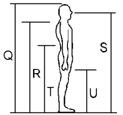
| Anthropometric | Men 5th | Men 50th | Men 95th | Women 5th | Women 50th | Women 95th |
|---|---|---|---|---|---|---|
| Q Stature | 64.6 in (164.1 cm) | 68.9 in (175.0 cm) | 73.3 in (186.2 cm) | 59.8 in (151.9 cm) | 64.0 in (162.6 cm) | 68.1 in (173.0 cm) |
| R Shoulder Height | 52.1 in (132.3 cm) | 56.2 in (142.7 cm) | 60.2 in (152.9 cm) | 48.0 in (121.9 cm) | 52.1 in (132.3 cm) | 56.3 in (143.0 cm) |
| S Eye Height | 60.1 in (152.7 cm) | 64.5 in (163.8 cm) | 68.9 in (175.0 cm) | 55.1 in (140.0 cm) | 59.4 in (150.9 cm) | 63.6 in (161.5 cm) |
| T Elbow Height | 39.6 in (100.6 cm) | 42.5 in (108.0 cm) | 46.1 in (117.1 cm) | 35.9 in (91.2 cm) | 39.1 in (99.3 cm) | 42.1 in (106.9 cm) |
| U Fingertip Height | 23.7 in (60.2 cm) | 26.0 in (66.0 cm) | 28.3 in (71.9 cm) | 21.3 in (54.1 cm) | 23.6 in (59.9 cm) | 25.9 in (65.8 cm) |
| Item | Add to | Height | Width | Length |
|---|---|---|---|---|
| Miner's Hard Hat | head | 2.0 in (5.1 cm) | 2.0 in (5.1 cm) | 2.0 in (5.1 cm) |
| Miner's Leather Boots | foot | 1.0-2.0 in (2.5-5.1 cm) | 1.0 in (2.5 cm) | 1.0 in (2.5 cm) |
| Miner's Rubber Boots | foot | 0.25 in (0.6 cm) | 0.25 in (0.6 cm) | 0.25 in (0.6 cm) |
| Light Gloves | hand | - | - | 0.25 in (0.6 cm) |
| Heavy Gloves | hand | 0.25 in (0.6 cm) | 0.5 in (1.3 cm) | 0.5 in (1.3 cm) |
| Battery Pack | hip breadth | - | 2.0 in (5.1 cm) | - |
| Filter Self-Rescuer | hip breadth | - | 3.5 in (8.9 cm) | - |
| Flame Safety Lamp | hip breadth | - | 2.0 in (5.1 cm) | - |
| Self-Contained Self-Rescuer | hip breadth | - | 3.0-5.0 in (7.6-12.7 cm) | - |
Additional space requirements for various items of personal protective equipment generally used in the underground work environment.
Enclosed Workstation Dimensions
The minimum interior height and length for fully or partially enclosed workstations depend on the operators' size, seated posture, seat design, and control inputs required. The illustrations below are for four seating space envelopes for 95th-percentile male and 5th-percentile female operators in 42-in (106.7-cm) and 22-in (55.9-cm) cab heights (1)
| A | Ankle Point |
|---|---|
| B | Knee Point |
| C | Hip Point |
| D | Shoulder Point |
| E | Shoulder Extended |
| F | Elbow Point |
| K | Standard Line-of-Site |
| L | Upper Line-of-Site |
| M | Lower Line-of-Site |
| R | Maximum Control Reach |
| S | Maximum Control Grip |
| T | Minimum Control Grip |
| Z | Minimum Display Distance |
| SRP | Seat Reference Point |
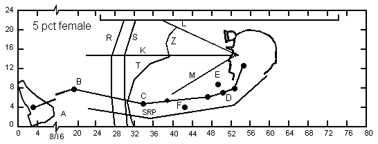
Seating space envelopes for 5th-percentile females in a 22-in cab height
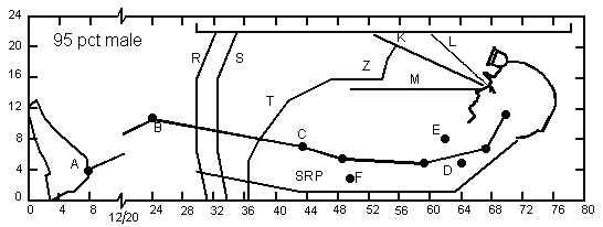
Seating space envelopes for 95th-percentile males in a 22-in cab height
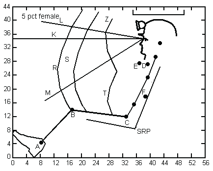
Seating space envelopes for 5th-percentile females in a 42-in cab height
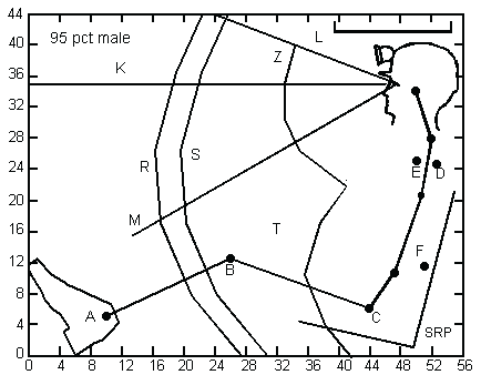
Seating space envelopes for 95th-percentile males in a 42-in cab height
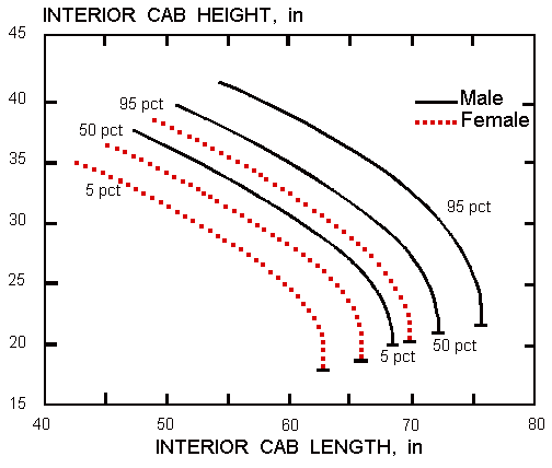
The figure below gives data on the interior workstation lengths and heights required to fit different sized operators. (1) The data are based on a 10 degree seat pan angle and a 2-in (5.1-cm) helmet clearance space under the canopy. It does not take into account the space needed to depress pedals or any additional space required for headrests or extra seat padding.
Seated posture, cab length, control placement, and the control actions affect the width of the workstation. Shoulder breadth and hip breadth are the relevant anthropometric dimension needed for establishing seated width requirements for normally seated or supine operators. For most individuals, shoulder width provides sufficient space to accommodate battery packs and small hand tools hung from the belt. For heavy individuals, hip breadth provides a starting point for determining the cab width. If operators sit cross-legged or with their knees to the chest, they require additional width. The table below summarizes the preferred workstation widths based on the 95th-percentile male. The values in the table are for individuals wearing light clothing and carrying battery packs.
| Seated Position | Rec. Width, 95th-Percentile Male |
|---|---|
| Normal Seated | 20.7 in (52.6 cm) |
| Cross Legged | 29.5 in (74.9 cm) |
| Knees to Chest | 24.6 in (62.5 cm) |
Recommended workstation widths
Workstation Ingress-Egress
For fully or partially enclosed workstations, the ingress-egress opening should permit rapid, unobstructed entry and exit. You should also incorporate the following entry design practices:
- Design and locate operating controls so that the operator cannot kick, bump, or inadvertently activate them when entering or leaving the workstation.
- Provide hand grip and footholds to ease entry and exit. This is especially important on machines designed for lower seams. Be sure that the hand grips and footholds do not interfere with emergency egress.
- Protect ingress-egress opening from potential fires or mechanical hazards. Design the entries to be free of blockage or obstructions created by machine parts if there is a collision.
- Provide an emergency escape hatch, opening, or route for enclosed workstations. The emergency escape route should exit toward the rear of the machine or toward supported roof.
Work Design
Workstation efficiency depends on the logical arrangement of tasks to enhance operator performance and reduce the chance of error. Properly associated controls and displays, logically grouping controls, and arranging controls to follow a natural sequence contribute to an efficiently operated machine.
As a workstation designer, you need to be aware of the subtle physiological stresses that result from simple design incongruities, such as lack of postural control, improper distribution of body weight, cardiovascular restriction, and fatigue inducing activity. Physiological factors, environmental stresses, and design features all interact, as shown in the table below. When using this table, keep in mind that gastrointestinal and cardiovascular disturbance minimizations should take precedence over musculoskeletal considerations in systems requiring long-term operator exposure. (2)
| Environment Considerations | Physiological System Affected - Musculoskeletal | Physiological System Affected - Cardiovascular | Physiological System Affected - Gastrointestinal |
|---|---|---|---|
| Vibration | 2 | 3 | 3 |
| Oscillation | 2 | 2 | 1 |
| Acceleration | 3 | 2 | 3 |
| Impact | 3 | 2 | 3 |
| Noise | 1 | 3 | 3 |
| Workstation Layout Considerations | Physiological System Affected - Musculoskeletal | Physiological System Affected - Cardiovascular | Physiological System Affected - Gastrointestinal |
|---|---|---|---|
| Poor distribution of operators body/limb weight | 1 | 2 | 2 |
| Improper postural support | 2 | 2 | 3 |
| Awkward body or limb positions | 1 | 3 | 3 |
| Frequent requirements to use maximum reach or force | 1 | 3 | 3 |
Relationship between operator physiological systems,
environment, and workstation layout
Rating criteria: 1 = critical, 2 = important, 3 = minor
Try to create a workstation that will maximize user acceptance. You will better motivate operators if their workstation is well-organized, convenient, simple, reliable, safe, and attractive. A disorganized, inconvenient, or unattractive workstation will frustrate them. You will reduce the operators' motivation to work if they have difficultly getting into position, or seeing or reaching controls because of poor arrangement.
Operator Protection
The following design recommendations focus on improving protection and efficiency. You should try to incorporate them, whenever possible, into the design of workstations.
Operator Positioning
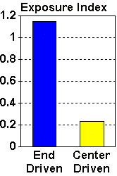 Position the workstation to take advantage of the protection provided by the frame of the vehicle. This recommendation is based on a study that found that center-driven shuttle cars generally offered less exposure to accidents than end-driven ones. (6) The study used an Exposure Index to compare the locations of shuttle car operator workstations. The Exposure Index is the ratio of the percentage of total accidents involving a given workstation location to the percentage of the total vehicle population having that workstation location. This technique assumes that the employees' hours of exposure for each workstation position would be directly proportional to its percentage of the vehicle population. The study found that end-driven shuttle cars had an Exposure Index five times that of center-driven shuttle cars.
One explanation for the increased safety in center driven designs are that the shuttle car frame acts as a warning device. It will contact ribs, brows, etc. first, and by that serve as a bumper or buffer zone for the operator. Also, end driven vehicles are generally more difficult to control on rough roadways since the operator is farther from the axis of the pitching movement. This transmits more shocks and vibrations to the workstation.
Protective Canopy
Equip the workstation with a protective canopy as required in Section 75.2720-1, Title 30 of the Code of Federal Regulations. The protective canopy should cover the minimum defined areas as defined in the regulations, or as much of the operator's body as practical consistent with the visual requirements for the machine's operation. Support structures for the protective canopy should not protrude into the workstation.
Limited-coverage canopies can provide partial operator protection for miners working in situations where conventional full-coverage canopies cannot be employed. (5) The basic advantages of these types of canopies are:
-
Protection from pinching or squeezing accidents/injuries.
-
Greater visibility of roof and working areas compared with full-coverage canopies, resulting in safer operation.
-
Operator exits have minimal obstructions, affording quick exit if necessary.
The example below illustrates a roll-bar-type protective structure. This type of protection is recommended only for the most restrictive environments (seam heights less than 42-in (106.7-cm)), where more comprehensive protection cannot be provided. Roll bars can provide protection and maintain reasonable operator visibility in all but the lowest coal seam applications (less than 32-in (81.3-cm)) where batch-type haulage is commonly applied. (5)
The main goal of this roll-bar-type protective structure is to prevent pinching or squeezing accidents. The roll bar should therefore be placed in front of, instead of directly over, the operator's head. (This is illustrated by the roll bar surrounded by the red box in the photo.) The next consideration is to place the roll bar so that it inhibits the operator from leaning out of the workstation. (The second roll bar in the photo, highlighted by the blue box, is for the other seat on this shuttle car.)
Incursion Protection
Where possible, provide safety panels, heavy mesh screens, or other protective devices to protect the operator from rib rolls, collisions with pillars while turning, or pinch points on the machine. These protective devices should not affect on the operator's visibility and not impede ingress and egress.
Exposure of Operator's Body
Design the workstation to ensure that you expose no parts of the operator outside its confines (excluding the canopy, as mentioned in the section above) during normal operation.
Extension of Canopy and Floor
Extend the side of the canopy and the operator's compartment floor a minimum of 10 in (25.4 cm) beyond the side of the machine if you require the operator to look down the side of the vehicle or to reach out from under protection to do job-related tasks.
Operator Head Clearance
Provide a minimum 2-in (5.1-cm) clearance between the top of the miner's hard hat and the underside of the operator's compartment or the tram stations roof.
Panic Bars
Equip each workstation with a panic bar, emergency cutoff switch, or button that the operator can readily activate using gross hand or foot movements. Install a panic bar so that entrapment cannot occur if the moving machine or a machine component (such as a swinging conveyor) could trap the operator against the face, rib, or side of the machine itself.
Interlock Switch
Use an interlock device to prevent movement of the machine or its components if the operator has left the designated operating area.
Operator Restraint Device
Install seat belts, access opening safety chains, doors, or other appropriate restraint devices to prevent the operator from falling or being thrown out of the machine while it is moving, or in case of collision.
Protection From Spillage and Workstation Cleanliness
Provide guards to protect the operator from spillage while loading, transporting, or discharging materials. Also, it is not difficult for coal and other materials to accumulate on the floor of the workstation. This buildup, if serious enough, can restrict pedal movement and lead to safety hazards and operator dissatisfaction. The floors of workstations should include grating near the pedals to prevent the buildup of dirt and debris. Cover wheels and tracks of vehicles to prevent road debris from being thrown at the operator.
Noise Protection
The following recommendations should help in protecting the operator from excessive noise:
-
Potential noise in the workstation area should be determined according to CFR 30, Part 70, Subpart F (Noise). You should also identify sources of excessive noise.
-
Protect the workstation, where possible, from direct exposure to high noise sources by isolations, deflective shields, or other components.
-
Design the workstation so as not to entrap noise or to reflect secondary sources of noise into the compartment. Install sound absorption and control materials where appropriate.
- If you cannot reduce the interior sound levels to permissible levels during certain machine operations, post signs conspicuously within the seated operator's primary field of view stating that noise levels exceed permissible levels during these operations and cautioning the operators to wear hearing protection.
Thermal Protection
The hydraulic fluid used in the power systems of mining machines can get very hot at times, especially those not using heat exchangers. Maximum allowable temperatures should be established for exposed equipment surfaces and for any fluids conveyed in lines subject to rupture. This is especially important in the vicinity of the operator's workstation.
Warning Devices
Equip machines that have movable appendages, such as conveyor booms or auger devices, with audible and/or visual warning devices to signal impending movement. Sometimes it may be prudent to incorporate a short delay between the activation of the warning device and the movement of the appendage to allow time for workers to get clear of any hazards.
Standardization
Try to be aware of previous workstation layout solutions, especially those that reflect the guidelines and specifications set out by recognized standards organizations, such as the Society of Automotive Engineers. Standardizing workstations provides several important benefits, including reduction in training time, less chance of operator error due to transferring from one machine to another, cost saving in the development of new hardware, and simplified maintenance for the end user. However, you should recognize the danger in duplicating a poor design concept to avoid thoroughly analyzing the operators' requirements and developing a proper solution.
References
- Sanders, M. S., and J. M. Peay. Human Factors in Mining. USBM IC 9182, 1988, 153 pp.
- Joint Army-Navy-Air Force Steering Committee. Human Engineering Guide to Equipment Design. John Wiley and Sons, 1972, 752 pp.
- Gilbert, V. A. Research Support for the Development of SAE Guidelines for Underground Operator Compartments (contract H0308110, Society of Automotive Engineers, Land & Sea Division). USBM OFR 8-91, 1990, 211 pp.; NTIS PB 91-146142.
- Applied Science Associates, Inc. Standardization of Controls for Underground Electric Face Equipment - Phase I (contract H0230021). USBM OFR 15-74, 1973, 105 pp.
- Bartels, J. R., A. J. Kwitowski, and W. D. Mayercheck. Protective Structures for Low-Coal Shuttle Car Operator. USBM RI 9143, 1987, 22 pp.
- Theodore Barry & Assoc. Equipment Operation Safety Study (contract S0110601). USBM OFR 24-72, 1972, 134 pp.; NTIS: PB/211-472.
- A Checklist for Evaluating Cab Design of Construction Equipment
- Control Design Principles
- Ergonomic and Existing Seat Designs Compared on Underground Mine Haulage Vehicles
- Experiments on Personal Equipment for Low Seam Coal Miners: IV. Incorporating Coiled Cord Into Cap Lamp Battery Cords
- Inexpensive, Easy to Construct Materials-handling Devices for Underground Mines
- Job Design: An Effective Strategy for Reducing Back Injuries
- Laboratory Investigation of Seat Suspension Design Performance during Vibration Testing
- Seating Design Principles
- Self-Reported Musculoskeletal Symptoms Among Operators of Heavy Construction Equipment
- Systematic Comparison of Different Seats on Shuttle Cars Used in Underground Coal Mines
- Task Analysis
- Transverse-Mounted End-Cab Design for Low-Coal Shuttle Cars