HASARD - An Electromagnetic-Based Proximity Warning System
- Introduction
- Background
- HASARD - Electromagnetic-Based Proximity Warning System
- Laboratory Testing of the Hasard System
- Recommendations and Enhancements - HASARD System
- HASARD Application Synopsis
- Conclusions
- Patent and Licensing Information
- References
- Appendix A - HASARD Field Test Data on Conveyor at Quarry
- Appendix B - HASARD Field Test Data on Rear of Haul Truck
Introduction
This document details the original development by the NIOSH Office of Mine Safety and Health Research of a novel electromagnetic-based proximity warning (PW) system to warn underground coal miners whenever they get too close to continuous mining machines. Its utility, shown by the early tests of the system, resulted in its potential application to other worker safety situations including surface mining operations (i.e., haul trucks, highwall mining), highway work zone equipment (e.g., trucks, transfer vehicles, rollers, pavers), conveyor belt operations, and construction machinery (e.g., forklifts, trucks, cranes).
The system was named Hazardous Area Signaling and Ranging Device (HASARD). Fundamentally, HASARD consisted of a low-frequency (LF) transmitter, one or more antennas (positioned at known dangerous areas) mounted on a continuous miner (CM), and a receiver which would be worn by each worker. The receiver accurately measured the magnetic field strength being generated by the LF transmitter and antenna. The antennas used in the transmitter and receiver were of the loop type, which made them predominately magnetic field antennas. Electric field antennas were not used because the electric field would be greatly affected by nearby objects. Basically, HASARD used the LF magnetic field as a marker for known dangerous work areas. The use of a LF magnetic field was advantageous because it provided a consistent stable magnetic field that was minimally affected by the environment (e.g., dust, dirt, water, humidity, cables, metal structures). Additionally, the magnetic field decayed in a very predictable manner (i.e., inverse cube relationship with respect to distance between the antenna and the receiver) and consequently provided a means of accurately measuring the distance between the worker and the dangerous area on the machine.
Note: Click on images to view a larger version.
Background

Figure 1
Mine worker crushed between a continuous mining machine and a coal rib
Remote-control CM operators and their helpers, preoccupied with production when operating their equipment, may unintentionally put themselves into potentially hazardous situations (Figure 1). Their attention is divided among maintaining production goals, watching out for their own safety, and processing the visual, tactile, and auditory cues that enable them to make informed decisions. The machine operator may find himself hurried, mentally overloaded, and unable to process information necessary to make the appropriate decisions. Both operators and helpers perform their everyday jobs, making choices and decisions that they may not consciously think about. While performing tasks, they are continually processing feedback and cues that guide them for the next move. Unfortunately, operators have the tendency to step alongside a moving CM or beyond the supported roof for a better view while coal cutting or tramming. The restricted workspace and reduced visibility in the mine work environment put the CM operator and helpers in awkward work postures for the job, with tasks requiring quick reactions to avoid being struck by moving machinery. Overwork, fatigue, risk taking, and continual changes in the workplace environment combine to heighten the probability of behavior that can result in serious injury or death [Burgess-Limerick and Steiner 2006; Bartels et al. 2008].
Each industrial work setting has its own set of worker safety issues. A sampling of statistics was collected to identify the need and to provide the justification for the application of HASARD to those work settings. For example, the Mine Safety and Health Administration (MSHA) data from 2004 showed there were approximately 41,000 underground mine workers and about 4,900 underground mine contract workers, making a total of 45,900 employees. MSHA accident data from 2002-2006 indicated that the coal industry averaged 6,407 accidents per year in underground mines. Twenty-one percent (1,345) of those total accidents per year involved mobile face equipment that included CMs, roof bolters, and haulage vehicles for underground mines. Four percent (286) of those total accidents per year occurred while operating continuous mining machines.
Between 1984 and 2010, the mining industry had experienced 33 underground coal mine fatalities directly associated with remote-controlled continuous mining machines (Figure 2). Currently, over 95% of the CMs in use in underground coal and trona mines are operated by remote control. MSHA has recently written two detailed reports on fatal accidents involving remote-controlled continuous miners (RCCMs). Remote Control Fatal Accident Analysis Report of Victim's Physical Location With Respect to the Mining Machine [MSHA 2009] discusses the victim's physical location with respect to the mining machine, and Remote Control Continuous Mining Machine Crushing Accident Data Study [MSHA 2006] identifies norms and trends in RCCM pinning, crushing, and striking accidents as part of MSHA's efforts to reduce and eliminate these types of accidents. MSHA found that tramming the machine to a new location was the most dangerous work function (26 out of 33 fatalities) and performing maintenance was the second most dangerous work function (6 out of 33 fatalities). MSHA also reviewed 67 nonfatal RCCM accidents that occurred from 1999-2004 and found that approximately half of the accidents occurred while the RCCM was being moved from one location to another.
![Locations of fatalities around a CM (1984-2009 MSHA data) Note: Circles represent machine operator; squares represent other miners; white background represents tramming accidents; gray background represents performing maintenance [MSHA 2010]](../../../UserFiles/content/machinesafety/hasard/Fig2.png)
Figure 2
Locations of fatalities around a CM (1984-2010 MSHA data)
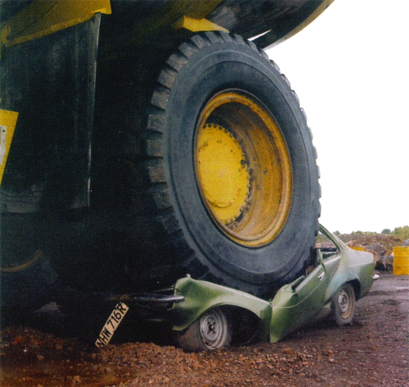
Figure 3
Large dump truck driving over smaller vehicle
The MSHA data from 2004 showed there were approximately 180,000 surface mine workers and about 67,000 surface mine contract workers, making a total of 247,000 employees. MSHA accident statistics (2000-2004) indicated that a major safety problem in surface mining was workers becoming injured, permanently disabled, or killed by moving machinery (about 3,000 lost-time injuries per year) and powered haulage (over 3,150 lost-time injuries per year). A review of MSHA surface mining fatalgrams (2000 to mid-2006) showed that there were 22 fatalities involving blind areas—38% associated with trucks and 33% with front end loaders [NIOSH 2007]. About 67% of these fatal accidents occurred while backing. These surface mining accidents frequently involved large dump trucks that drove over a smaller vehicle (Figure 3) or a worker who was in a blind spot of the truck. It is believed that over half of these accidents could have been avoided if the equipment operator had been adequately warned of the impending collision.
Conveyors are one of the most efficient methods to move material. Mechanical conveyors, whether package, bulk, or unit, are used in nearly all industrial plants, and they are essential to most production processes. Unfortunately, Bureau of Labor Statistics data indicate that for 2001-2005 there have been more than 20 fatalities and over 3,000 injuries every year nationwide due to conveyor accidents, with powered conveyors being the primary source of injury [BLS 2005]. In the mining industry there were 17 fatalities and over 1,500 lost-time, conveyor-related injuries during 2001-2005 [MSHA 2005]. Head pulleys, carrier rollers, drive motors, automatic tensioning devices, scalpers, and belt alignment all present their own form of danger to operators and maintenance workers.
In 2002 in the construction industry, according to the American Road and Transportation Builders Association, there were approximately 575,000 highway and street construction workers employed in the private sector. These roadway construction workers were at risk of fatal and serious nonfatal injuries when working near passing motorists, construction vehicles, and equipment. From 1995-2002, 844 of these workers were fatally injured. In about 55% of these cases, the death was either vehicle- or equipment-related and either clearly or probably occurred inside the work zone. In 68% of the vehicle- and equipment-related fatalities within work zones, a worker-on-foot was struck by a vehicle. Victims were just as likely to be struck by a construction vehicle as by a passing traffic vehicle [NIOSH 2001].
HASARD - Electromagnetic-Based Proximity Warning System
In 1998, MSHA requested that NIOSH researchers develop a PW system that could be used to reduce the number of injuries and fatalities of miners near CMs. A review of the literature and preliminary testing of a sampling of commercially available proximity detection systems failed to identify any system that could provide the reduction of human risk around mining equipment. At that time, the available systems were passive and subject to alarming when a worker was not necessarily in any danger. Any object in the path of a CM would trigger an alarm. A worker who continuously heard alarms when in no perceived danger would tend to ignore an alarm even when in danger [Blackmon 1995].
Based on a review of existing proximity detection technologies (as of 1998), NIOSH researchers concluded that a more robust methodology would be required. NIOSH had previous experience with LF magnetic-based technology, which they identified as a good candidate for working successfully in a wet, dirty, dynamically changing underground coal mine environment. Additionally, NIOSH recognized that a passive style system was fundamentally flawed for use in the close confines of a coal mine face area, since the workers are always in close proximity to the machines, the mine ribs, and numerous other objects. A set of design criteria was developed for the system that included two important precepts: robustness and non-passive or active sensing.
The initial prototype consisted of a transmitter on the machine and a receiver on the worker. The system was named Hazardous Area Signaling and Ranging Device (HASARD) [Schiffbauer 1999; Schiffbauer and Mowrey 2001; Schiffbauer 2002; NIOSH 2009]. The proposed system evolved and ultimately resulted in NIOSH personnel producing a robust, effective, and potentially life-saving safety device. NIOSH then licensed the resulting technology to a number of companies. At the beginning of this project (1998) there were no MSHA-approved systems available for use in underground coal mines. Near the conclusion of this project, Geosteering Mining Services of Frederick Mining Controls obtained the first MSHA approval for use of the device on CMs in underground coal mines. Geosteering called the system TramGuard™.
TramGuard™ generated a magnetic marker field around a continuous mining machine, which was then detected by personal alarm devices worn by mining personnel and warned the operator or other miners with an audible sound. A display mounted on the continuous mining machine also visually warned the miners when they came inside the turning radius of the continuous mining machine. Another goal of the system was to help train operators and other miners to stay clear of the hazards around the continuous mining machine. If the continuous mining machine was closer to a miner than a specified distance, the TramGuardTM system would stop the continuous mining machine tram motors and the hydraulic booms.
In November 2005, the TramGuard™ system completed a successful field trial at Consol of Kentucky Inc.'s Jones Fork E-3 Mine. During this field test, the system provided consistent warning and shutdown commands and effectively prevented an operator wearing a personal alarm device from entering the hazardous area around the machine. The TramGuard™ system components were approved by MSHA as complying with the applicable provisions of Title 30 Code of Federal Regulations (30 CFR) Part 18. A Program Informational Bulletin P06-03 was issued on February 2, 2006 informing the mining industry of the development and availability of this proximity protection system that can be installed on remote control continuous mining machines, and Geosteering then began actively marketing their product.
Since then, two other companies have developed MSHA-approved PW systems that work on the same principle as HASARD. Frederick Mining Controls developed a system similar to Geosteering called HazardAvert. Nautilus International Control & Engineering, Ltd., developed the Coal Buddy System in 2006, and Matrix Design Group developed the Model M3-1000 Proximity Monitoring System in 2009. These MSHA approvals ensure that these systems will not introduce an ignition hazard when operated in potentially explosive atmospheres. Links to these and other developers of currently available proximity detection and collision avoidance systems can be found on MSHA's "Proximity Detection/Collision Warning Single Source Page" [MSHA 2010].
HASARD design criteria encompassed the following:
- Sensing the presence of a miner in a known potentially dangerous ("risk") zone in the vicinity of the continuous mining machine.
- Providing some type of visual/audible/tactile warning alarm and/or stopping the CM when the miner entered a "risk" zone.
- Being simple to operate and maintain.
- Being reliable.Being a non-passive (active) system.
- Employing magnetic fields as a marker.
- Being sufficiently rugged to survive normal mining operations.
- Being difficult to defeat, bypass, or disable.
- Being capable of failing in a safe manner.
- Not giving a false positive alarm when an object (e.g., rock or coal, other equipment) entered the "risk" zone.
- Not presenting a nuisance to the miner.
As developed, HASARD was an active PW system. The active feature was very important and was somewhat unique since most PW systems at the time of the design were of the passive type. Passive types of PW systems would be triggered by all objects detected within their useful range, which was not always desirable. This was especially true in underground remote-controlled continuous mining coal operations. In these situation, operators and helpers worked in close proximity to CMs as well as to the walls (ribs) of the mine. A passive system would be triggered every time it detected a wall or a person. If the system triggered with every large object it detected, it would become a nuisance to the operator, causing him/her to tend to ignore the system. HASARD, being an active-type system, could minimize or eliminate such nuisance alarms. HASARD required a transmitter on one object and a receiver on another object. In this way, objects to be avoided would be positively identified and would thereby correctly trigger the system. Conversely, objects that didn't need to be avoided would be ignored by the system. In the underground mining scenario with a transmitter on the CM and the receiver on the person, the HASARD system could keep the person from being crushed but would still allow the operator to tram the CM close to the rib.
HASARD consisted of four components, a transmitter (Figure 4), an antenna (Figure 5), a receiver (Figure 6), and a base station/control box (Figure 7). An initial version of the system consisted of placing the transmitter on the person with the receiver on the CM. All later versions consisted of placing the transmitter and associated antenna on the equipment, vehicle, or dangerous work area to be marked; the receiver was worn either by a worker or mounted on a pendant or on another vehicle. The fourth part of the system (the base station/control box) was used when a remote alarm, a data logger, and/or a controlled machine response was desired.
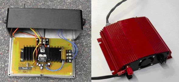
Figure 4
HASARD transmitter

Figure 5
Multiconductor wire loop antenna stretched around machine. The Ferrite Bar Antenna is shown in the inset
The HASARD transmitter generated a continuous sinusoidal, 73-kHz electromagnetic field using one or more wire loop or ferrite bar antennas. This frequency was selected since it was found that continuous mining machines generated considerable electrical noise up to, and sometimes beyond, 30 kHz. Other control and communication devices employed underground generally used frequencies of 88 kHz and above. Also, at the time of selection, the Federal Communications Commission permitted the use of 73 kHz for amateur experimentation. Other frequencies in the LF range (30-300 kHz) could have been selected. However, as the medium frequency (300 kHz to 30 MHz) band of signals was approached, the signal would begin to couple and attach itself to surrounding metallic conductors. This coupling was not a desirable feature for creation of a stable and robust marker since the source (point of origin) of the signal would then become obscure.
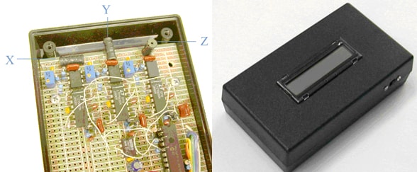
Figure 6
Prototype HASARD receiver
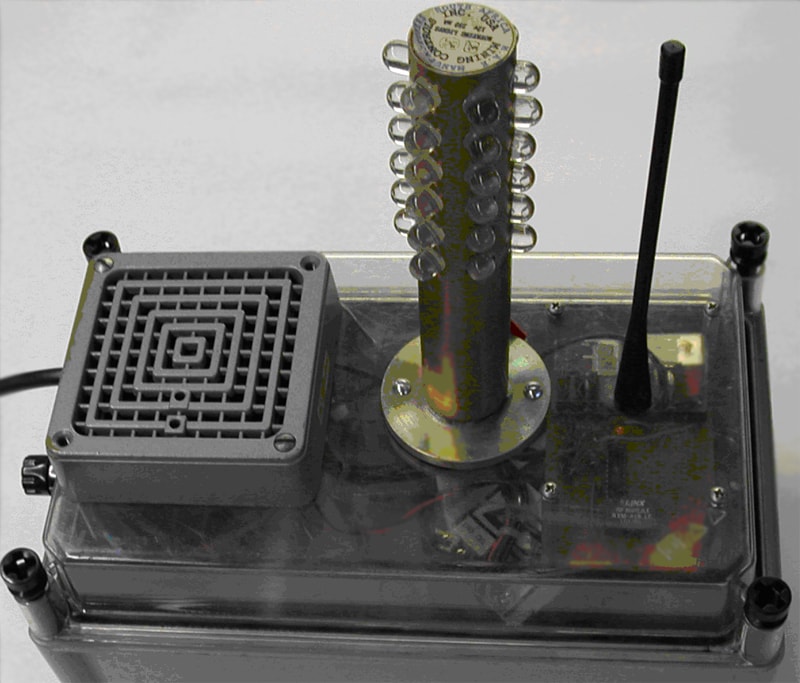
Figure 7
Base station/control box
Basically, the HASARD transmitter is more like the primary side of a transformer than a transmitter. Consequently, it may be more appropriate to call the HASARD transmitter a generator; however, for consistency in this document the term transmitter will be used. A generalized block diagram of the HASARD transmitter is shown in Figure 8. A sine wave generator chip, as opposed to a square wave generator chip, was employed. A square wave signal contains many harmonics which would spread the useable power over a range of frequencies, which was not energy efficient. The power amplifier was a single-chip, 30-watt, audio amplifier, which was efficient at 73 kHz. A gain adjustment was provided for setting the power output to the chosen level. Many variations of this fundamental design were prototyped. One HASARD version included a microprocessor chip for frequency selection, unique signal identification (ID), power regulation, and adjusted current output.
The antennas developed for HASARD consisted of wire loops or ferrite rods with wire wrapped around them. For clarity, they are described either as a wire loop or as a ferrite rod antenna. The wire loop antenna could be stretched around the periphery of the machine (Figure 5) or multiple small loops could be placed on specific dangerous areas of the CM. The loop antenna could be adjusted to establish a contoured magnetic field pattern for each hazardous area. A ferrite rod antenna, which consisted of a wire wrapped around a ferrite core (inset in Figure 5), could be encased in a polyvinyl chloride (PVC) pipe, which, in turn, would be mounted on a dangerous area of the equipment. Alternatively, the ferrite rod could be enclosed in an aluminum and Lexan enclosure.
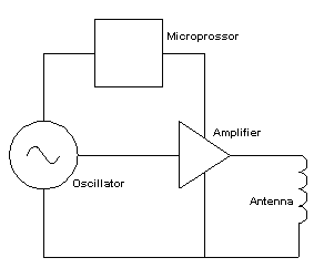
Figure 8
Block diagram of HASARD transmitter
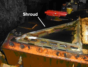
Figure 9
Protective metal antenna shroud
Wire loop antennas for the HASARD system were generally composed of an MSHA-approved SOW-A 90C (SO) cable, which was a 3-conductor, 14-gauge cable. The antenna was draped around the area of the CM that needed to be avoided (Figure 5). It should be noted that some on-site experimentation needed to be performed on the CM in order to determine how many turns of the SO cable would be required to set up an appropriate magnetic field of sufficient strength. Additionally, a protective metallic shroud needed to cover the SO cable (antenna) to protect it from falling rocks and other sources of potential damage (Figure 9). Once the antenna was attached to the machine, special high-voltage, polypropylene capacitors were used to tune the antenna so that it resonated at exactly 73 kHz.
The amount of transmitter current and the antenna layout (i.e., antenna mounting position and physical geometry) were then adjusted at the site to establish a stable and predictable magnetic field pattern for the hazardous area around the machine. Multiple wire loops could be implemented on one CM. Experiments showed that the magnetic marker remained stable even when covered with tons of rock or exposed to water sprays. The generated magnetic field decayed in a predictable manner, i.e., approximately falling off as an inverse cube relationship (1/r3) as shown in Figure 10. It was this predictability which made HASARD a robust marker and very accurate distance-determining device, particularly at short distances.
Ferrite rod antennas for HASARD are much easier to implement in the field than wire loops. Compared to a wire loop, ferrite rod antennas can be made much smaller and can generate a reasonably sized footprint. They should be tuned prior to installation, since the magnetic field is contained around the ferrite rod and not around the metal mass of the machine. The ferrite rod should be specially selected (best permeability and least eddy current loss) to handle the desired current and the frequency of operation. An insulated, wide and flat braided wire is generally used to wind the coil around the ferrite rod. A flat wire is used to equally distribute the current over the length of the ferrite, which minimizes hot spots and maximizes power efficiency. As mentioned above, special high-voltage, polypropylene capacitors should be used to tune the ferrite rod so that it resonates at exactly 73 kHz. The completed antenna would next be placed on the appropriate area of the machine. One or more of these antennas (ferrite rods) could be placed around the machine. The length of the ferrite rods used for HASARD was 12 in, which is long enough to generate a reasonably sized magnetic marker, yet short enough to minimize directivity.

Figure 10
Magnetic field decaying as a function of distance from the antenna
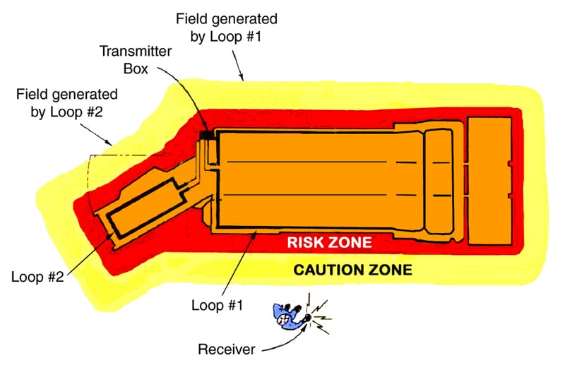
Figure 11
HASARD system using two wire loop antennas mounted around the body and tail of a CM
The receiver (Figure 6) could be worn on the miner's belt, in the pocket, or mounted on a remote control pendant. It consisted of an accurate 3-axis magnetic field strength meter with a wireless data-link. The received signal was compared against preset levels that had been calibrated to identify two basic levels of alarm, namely "caution" and "risk" as illustrated in Figure 11. When the worker wearing the receiver intruded into the marked dangerous area, his receiver warned him of the danger. The receiver outputs included visual, audible, and vibratory indicators. In addition, an LCD display presented critical receiver parameters. The wireless data-link of the receiver, in combination with the base station/control box, provided for disabling one or more CM functions, e.g. stopping tramming, turning off pumps, and disconnecting electrical power. A block diagram of the HASARD receiver is shown in Figure 12.
The front end of the receiver consisted of three identical parallel circuits. Each had its own antenna, preamp, band-pass filter, and detector. The magnetic field generated by the antenna connected to the HASARD transmitter was developed in only one plane. In order to accurately measure the magnetic signal, it had to be measured in three planes (axes), and then a vector addition of the three signals provided an accurate result. One circuit measured the magnetic field in the X direction, one in the Y direction, and one in the Z direction. The magnetic sensing element for each of the three circuits was a small ferrite bobbin, which was tuned with a high-voltage capacitor to make it sensitive to only 73 kHz. The three ferrite bobbins were placed orthogonally and were separated to minimize mutual coupling. The preamps raised the signals to useable levels. To minimize noise interference and to capitalize on only the signal provided by the HASARD transmitter, the three circuits were intentionally not very sensitive.
Each receiver circuit also contained an active filter. The filter eliminated out-of-band signals, such as noise, and also helped emphasize the magnetic marker signal. It was desirable to have a filter with a very small bandwidth in order to achieve a more accurate and reliable system. The original filter used was the crystal type with a ±5 Hz bandwidth, but temperature variations caused unpredictable results. The filter design used was an 8th-order Bessel bandpass filter with a bandwidth of 4 kHz. Although this filter design was acceptable, it was not optimal. Alternatively, a DSP filter could have achieved the desired few Hz bandwidth, but the complexity of the design and the higher power requirements were not practical.
The detector of each circuit was a simple full-wave detector that used germanium diodes instead of silicon diodes. Germanium diodes have a much lower forward voltage drop than silicon, which presented a higher effective output signal to the circuitry that followed. The circuit design objective was to achieve the highest possible direct current (DC) voltage output with the lowest possible input signal. This made it easier for the microprocessor circuitry to derive the maximum possible range using the available signal. Alternatively, Schottky diodes or a more elaborate detector design could have been employed. Also, the detector could have been eliminated if a microprocessor having a much faster sampling rate was employed, but this wasn't an option at design time.
The three detectors presented the microprocessor with three DC voltages representing the magnetic field in each of the X, Y, and Z axes. The microprocessor performed a vector addition of the three voltages, which was an accurate representation of the magnetic field. The microprocessor compared the magnetic field level with preset values that represented the "caution" and "risk" zone distances from the HASARD marker. As the magnetic signal reached the "caution" level, the microprocessor activated a vibrating motor or an audible buzzer or an LED. When the "risk" level was reached, the microprocessor activated a vibrating motor and a wireless link.
The wireless link functionality evolved throughout the project. Initially, it consisted of a single chip data encoder with a simplex ultrahigh frequency (UHF) transmitter. The UHF antenna was the short stubby type. Later, the wireless link consisted of a duplex spread spectrum transceiver with a serial interface to the microprocessor chip. In all cases, the critical data from the HASARD receiver was conveyed to the base station/control box using this link. Some of the data bits conveyed over the link included "receiver ID," "caution," and "risk" alarms.
The fourth part of the system was the base station/control box (which will be called the base station). A block diagram of the base station is shown in (Figure 13). The base station went through many design changes. It was constructed for use both offboard as well as onboard the machine. The base station was the central wireless data link for collection/access to all the man-carried receivers. The base station also provided visual and audible alarms in response to miner-carried receiver activity. Additionally, the base station provided the ability to shut down the machine to which it was attached. Features that were conceptualized but not fully implemented into the base station included time-of-entry into a zone, time-of-exit from the zone, distance-to-machine, machine ID, receiver battery life, machine-to-machine communications, record archiving, and black box (data recording) functionality.
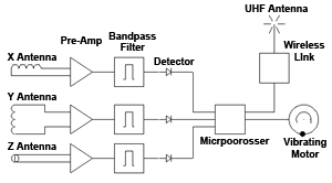
Figure 12
Block diagram of the HASARD receiver
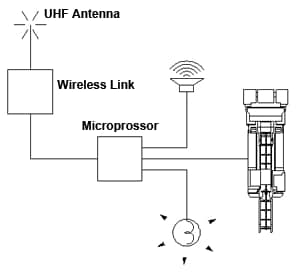
Figure 13
Block diagram of the HASARD base station/control box
The HASARD system, as it has been described in this document, was unique to the industry as acknowledged through the granting of two patents: (1) "Mobile Machine Hazardous Working Zone Warning System" U.S. Patent No. 5,939,986, which was issued on August 17, 1999, to William H. Schiffbauer and Carl W. Ganoe and (2) "Non-directional Magnet Field Based Proximity Receiver With Multiple Warning and Machine Shutdown Capability" U.S. Patent #6,810,353 B2, which was issued on Oct. 26, 2004, to William H. Schiffbauer.
Laboratory Testing of the Hasard System
Wire Loop Antenna Configurations
Free Space Tests
As the HASARD system was being developed at NIOSH, various loop antenna configurations and shapes were built and evaluated at the NIOSH Pittsburgh surface test facility. The first set of tests consisted of measuring the magnetic field strength at various distances in "free space" for several basic geometries, e.g., circular loop; rectangular loop, vertical; and rectangular loop, horizontal.
All wire loop antennas were constructed from MSHA-approved three-conductor, No. 14 American Wire Gauge (AWG), SO cable. The loops consisted of one to three or more turns of SO cable. The number of turns was dictated by the required size of the magnetic field. The magnetic field produced by the antenna is generally referred to as the magnetic moment (m) expressed in amperes-square meter (Am2) [Fink and McKenzie 1975].
m = INA
where m is the product of the current (I) in amperes, the number of turns in the loop (N), and the area (A) in square meters of a current-carrying loop. There is, however, a practical limit on the number of turns of wire in the loop. As the number of turns of wire increases, a point will be reached where the power begins to decrease due to long cable lengths and increased inductance, which limits the size of the magnetic moment.
The testing apparatus consisted of an arbitrary waveform generator (Wavetek Model 395), which was set to generate a constant 1-A sinusoidal current at frequencies of 125 kHz and 73 kHz. These two frequencies were selected since there appeared to be no other mining or electrical equipment that operated at or around either of these two frequencies. An oscilloscope (Tektronix THS 720A) and a true RMS voltmeter (Keithley 2000 multimeter) were used to verify that the signal produced by the arbitrary waveform generator was at the correct frequency and current level. Figure 14 shows a view of some of the test equipment used.
Two single-axis magnetic field measurement devices - the HP loop (Hewlett Packard, Emco Model 7605 magnetic field pickup coil) and the Holaday 3600 (Holaday Industries HI-3600 Radiation Survey Meter), Figure 15 - were used to record the magnetic values at various distances from the particular antenna configuration being tested. The HP loop is a device designed for measuring magnetic field in the frequency range of 20 Hz to 500 kHz to the specific limits in MIL-STD-461 [DOD 2007] in accordance with MIL-STD-462 [DOD 1967]. The radiation survey meter is designed to measure complex (nonsinusoidal) electromagnetic fields over a frequency range of 12 kHz to 200 kHz. It displays the RMS value of the electric and magnetic field strength components on a handheld LCD screen.
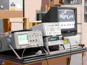
Figure 14
Laboratory test equipment setup for HASARD testing
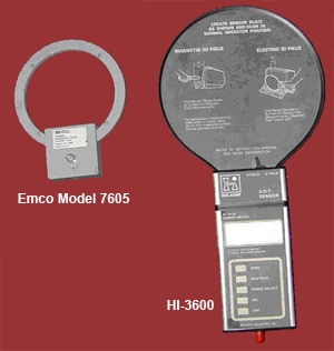
Figure 15
HP loop (Emco Model 7604 magnetic field pickup coil) and Holaday 3600 (Holaday Industries 3600 radiation survey meter)
Circular Wire loop Antenna Measurements in Free Space
An unshielded, 1-m circular wire loop antenna consisting of four wire loop turns was constructed on a plywood table (Figure 16) using MSHA-approved three-conductor, No. 14 AWG type, SO cable. The wire loop was oriented in a horizontal plane and elevated 4 ft above the concrete floor. The loop was then tuned to 125 kHz using an LCR meter (Sensore LC103). The tuning capacitance was 0.047 µF, and the measured inductance was 52.1 µH. A 51-Ω resistor was used to limit the current in the loop. The arbitrary waveform generator was set to 3.00 Vrms and the measured current in the wire loop was 58.0 mA.
The HP loop was then used to measure the magnetic field for each of the three orthogonal directions (X, Y, and Z) as shown in Figure 16. The starting distance ("0 in") from the center of the loop antenna to the center of the HP loop was approximately 30 in. The HP loop was rotated for each of the three axes. A total of six measurement points were taken (3 in, 6 in, 12 in, 24 in, 48 in, and 96 in). The results of these measurements are given in Figure 17. The X and Y orientations, as expected, essentially showed no (null) voltage, whereas the Z orientation (test measurement loop parallel to antenna loop in the X-Y plane) shows the typical magnetic field decay as a function of distance from the loop antenna.
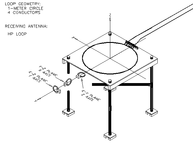
Figure 16
Test configuration showing the HP loop used to measure the magnetic field of a 1-m diameter circular wire loop antenna in free space
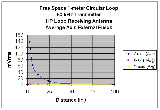
Figure 17
HP loop output as a function of distance from the 1-m circular loop
The Holaday 3600 was next used to measure the magnetic field in the same three orthogonal directions for the same loop antenna setup as shown in Figure 18. The starting distance ("0 in") from the center of the loop antenna to the center of the Holaday 3600 was approximately 30 in. The Holaday 3600 was rotated for each of the three axes. A total of six measurement points were taken (3 in, 6 in, 12 in, 24 in, 48 in, and 96 in). The results of the Holaday 3600 measurements are given in Figure 19. Similar to the HP loop results, the X and Y orientations essentially show no (null) or very little voltage, whereas the Z orientation (test measurement loop parallel to antenna loop in the X-Y plane) shows the typical magnetic field decay as a function of distance from the loop antenna.
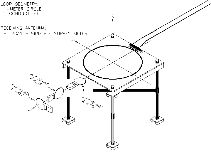
Figure 18
Test configuration showing the Holaday 3600 used to measure the magnetic field of a 1-m diameter circular wire loop antenna in free space
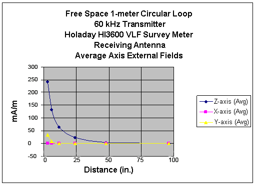
Figure 19
Holaday 3600 output as a function of distance from the 1-m circular loop
For comparison and correlation purposes, the measurements taken with the HP loop were compared with the measurements taken with the Holaday 3600 as shown in the linear plot in Figure 20. For example, a 2-mVrms reading on the HP loop corresponded to a 10-mA/m reading on the Holaday 3600, and a 7-mVrms reading on the HP loop corresponded to a 40-mA/m reading on the Holaday 3600. Likewise, a second set of comparison data was taken with the HASARD system and compared with the measurements taken with the Holaday 3600 as shown in Figure 21. For example, a 50-mVdc reading on the HASARD system corresponded to a 10-mA/m reading on the Holaday 3600, and a 210-mVdc reading on the HASARD system corresponded to a 40-mA/m reading on the Holaday 3600. Note: In most tests the HP loop was more convenient to use than the Holaday 3600 survey meter. The relationship between these two measurement instruments was obtained so that all HP loop data could be converted to magnetic field intensity units.
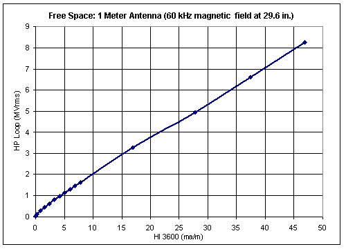
Figure 20
HP loop output vs. Holaday 3600 output
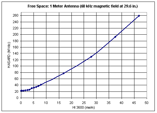
Figure 21
HASARD output vs. Holaday 3600 output
Vertically Mounted Rectangular Wire Loop Antenna in Free Space
An unshielded, 12x2-ft rectangular wire loop antenna consisting of three loop turns (two loops adding, one loop opposing) was constructed on PVC plastic tubing (Figure 22) using MSHA-approved three-conductor, No. 14 AWG, SO cable. The plane of the wire loop was vertical, and the top edge of the loop was elevated 4 ft above the concrete floor. The loop was then tuned to 125 kHz using an LCR meter (Sensore LC103). The tuning capacitance was 0.037 µF, and the measured inductance was 7.5 µH. A 48-Ω resistor was used to limit the current in the loop. The arbitrary waveform generator was set to 3.02 Vrms, and the measured current in the wire loop was 62.9 mA. The antenna was marked in two dimensions: height above the concrete floor and length along the rectangular loop. The four heights were HT#1 = 48 in, HT#2 = 36.5 in, HT#3 = 25 in, and HT#4 = 13.5 in. There were five measurement lines: ML#1, ML#2, ML#3, ML#4, and ML#5 at equally spaced, 3-ft increments along the rectangular loop; ML#5 was located at the generator input point and ML#1 was located at the opposite end of the loop.
The HP loop was then used to measure the magnetic field for each of the three orthogonal directions (X, Y, and Z) as shown in Figure 22. Measurements included taking the X, Y, and Z values at each of four heights (HT#1-¬HT#4) and five equispaced lines (ML#1-ML#5) out to a distance where the HP loop output was reduced to ambient background electromagnetic noise. The overall averaged result of the measurements at a height of 48 in (i.e., HP loop at same height as the top edge of the rectangular vertical loop antenna) is given in Figure 23. The fitted curve, based on the averaged values, was calculated to be Y = 1110X-1.75, with an r2 = 0.98.
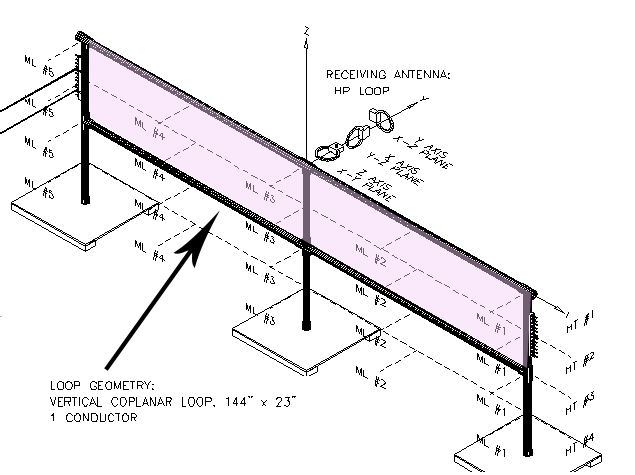
Figure 22
Magnetic field measurement points on a rectangular vertical wire loop antenna using the HP loop.
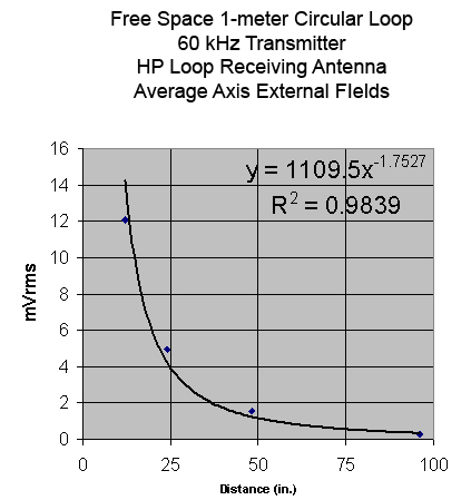
Figure 23
Magnetic field vs. distance from the rectangular vertical loop using the HP loop at a height of 48 in
The Holaday 3600 was next used to measure the magnetic field in the same three orthogonal directions for the same loop antenna setup as shown in Figure 24. Measurements included taking the X, Y, and Z values at each of four heights (HT#1-HT#4) and five equispaced lines (ML#1-ML#5) out to a distance where the Holaday 3600 output was reduced to ambient background electromagnetic noise. The overall averaged result of the measurements at a height of 48 in (i.e., Holaday 3600 at same height as the top edge of the rectangular vertical loop antenna) is given in Figure 25. The fitted curve based on the averaged values was calculated to be Y = 2594X-1.97 with an r2 = 0.95.
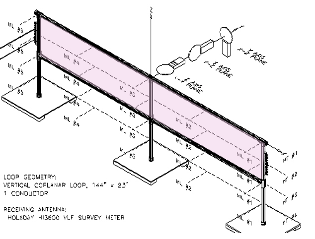
Figure 24
Magnetic field measurement points on a rectangular vertical wire loop antenna using the Holaday 3600
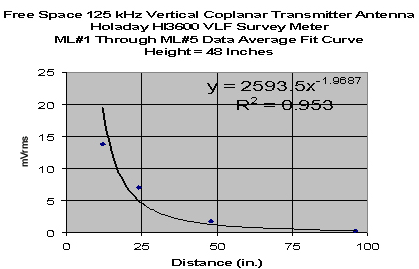
Figure 25
Magnetic field vs. distance from the rectangular vertical loop using the Holaday 3600 at a height of 48 in
Horizontally Mounted Rectangular Wire loop Antenna in Free Space
An unshielded rectangular wire loop antenna consisting of one turn was constructed on PVC plastic tubing (Figure 26) using MSHA-approved three-conductor, No. 14 AWG, SO cable. The wire loop was oriented horizontally, and the loop was elevated 4 ft above the concrete floor. The loop was then tuned to 125 kHz using an LCR meter (Sensore LC103). The tuning capacitance was 0.147 µF and the measured inductance was 11.0 µH. A 48-Ω resistor was used to limit the current in the loop. For this test, the arbitrary generator was replaced with the HASARD transmitter operating at 125 kHz, and its output was set to 4.03 Vrms. The measured current in the wire loop was 62.9 mA. The antenna was marked in two dimensions: height above the concrete floor and length along the rectangular loop. The four heights were HT#1 = 48 in, HT#2 = 36.5 in, HT#3 = 25 in, and HT#4 = 13.5 in. There were five measurement lines: ML#1, ML#2, ML#3, ML#4, and ML#5 at equally spaced 3-ft increments along the rectangular loop; ML#5 was located at the generator input point, and ML#1 was located at the opposite end of the loop.
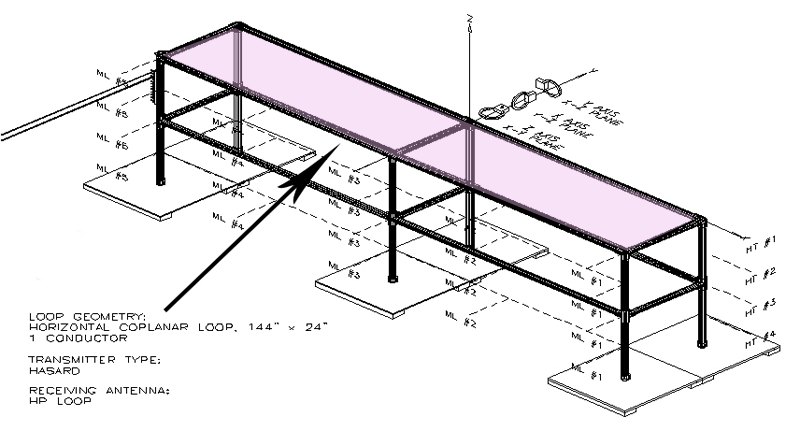
Figure 26
125-kHz magnetic field measurement points on a rectangular horizontal wire loop antenna using the HP loop
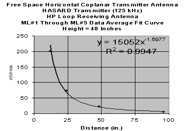
Figure 27
125-kHz magnetic field vs. distance from the rectangular horizontal loop using the HP loop at a height of 48 in
The Holaday 3600 was next used to measure the magnetic field in the same three orthogonal directions for the same loop antenna setup as shown in Figure 28. Measurements included taking the X, Y, and Z values at each of four heights (HT#1-HT#4) and five equispaced lines (ML#1-ML#5) out to a distance where the Holaday 3600 output was reduced to ambient background electromagnetic noise. The overall averaged result of the measurements at a height of 48 in (i.e., Holaday 3600 at same height as the top edge of the rectangular horizontal loop antenna) is given in Figure 29. The fitted curve based on the averaged values was calculated to be Y = 27673X-1.77 with an r2 = 0.99.
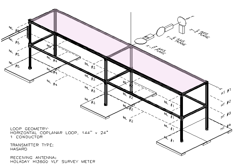
Figure 28
125-kHz magnetic field measurement points on a rectangular horizontal wire loop antenna using the Holaday 3600
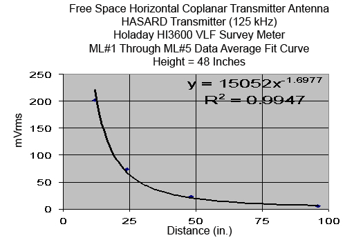
Figure 29
125-kHz magnetic field vs. distance from the rectangular horizontal loop using the Holaday 3600 at a height of 48 in
The frequency of the HASARD transmitter was next changed from 125 kHz to 73 kHz to see if there were any significant differences in the measured magnetic fields due to different operational frequencies. The tuning capacitor was also changed from 0.147 µF to 0.44 µF due to the change in frequency. For comparison purposes, the Holaday 3600 was used to measure the magnetic field in the same three orthogonal directions for the same loop antenna setup as shown in Figure 30. Measurements included taking the X, Y, and Z values at each of four heights (HT#1-HT#4) and five equispaced lines (ML#1-ML#5) out to a distance where the Holaday 3600 output was reduced to ambient background electromagnetic noise. The overall averaged result of the measurements at a height of 48 in (i.e., Holaday 3600 at same height as the top edge of the rectangular horizontal loop antenna) is given in Figure 31. The fitted curve based on the averaged values was calculated to be Y = 11988X-2.00 with an r2 = 0.98.
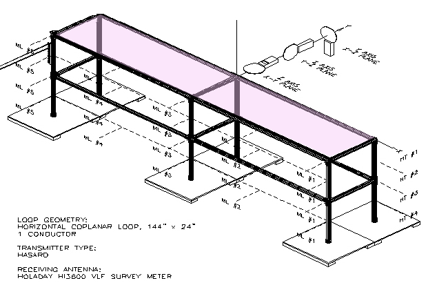
Figure 30
73-kHz magnetic field measurement points on a rectangular horizontal wire loop antenna using the Holaday 3600
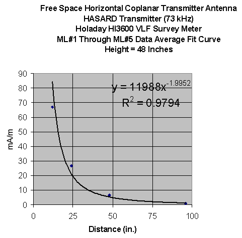
Figure 31
73-kHz magnetic field vs. distance from the rectangular horizontal loop using the Holaday 3600 at a height of 48 in
The HASARD receiver was next used to measure the magnetic field in the same three orthogonal directions for the same loop antenna setup as shown in Figure 32. Measurements included taking the X, Y, and Z values at each of four heights (HT#1-HT#4) and five equispaced lines (ML#1-ML#5) out to a distance where the HASARD receiver output was reduced to ambient background electromagnetic noise. The overall averaged result of the measurements at a height of 48 in (i.e., HASARD receiver at same height as the top edge of the rectangular horizontal loop antenna) is given in Figure 33. The fitted curve, based on the averaged values, was calculated to be Y = 93X-1.07 with an r2 = 0.75. The overall averaged result of the measurements at a height of 36.5 in (i.e., HASARD receiver at same height as the top edge of the rectangular horizontal loop antenna) is given in Figure 34. The fitted curve, based on the averaged values, was calculated to be Y = 264X-1.34 with an r2 = 0.89. The overall averaged result of the measurements at a height of 25 in (i.e., HASARD receiver at same height as the top edge of the rectangular horizontal loop antenna) is given in Figure 35. The fitted curve, based on the averaged values, was calculated to be Y = 139X-1.21 with an r2 = 0.89. The overall averaged result of the measurements at a height of 13.5 in (i.e., HASARD receiver at same height as the top edge of the rectangular horizontal loop antenna) is given in Figure 36. The fitted curve based on the averaged values was calculated to be Y = 103X-1.17 with an r2 = 0.89.
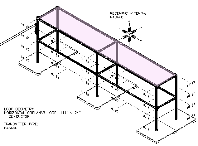
Figure 32
73-kHz magnetic field measurement points on a rectangular horizontal wire loop antenna using the HASARD receiver
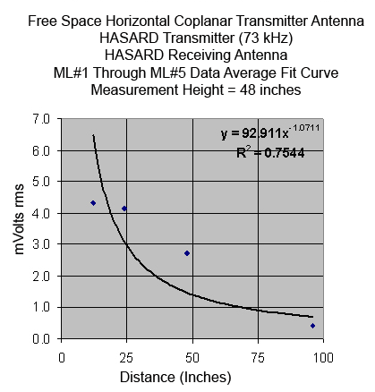
Figure 33
73-kHz magnetic field vs. distance from the rectangular horizontal loop using the HASARD receiver at a height of 48 in
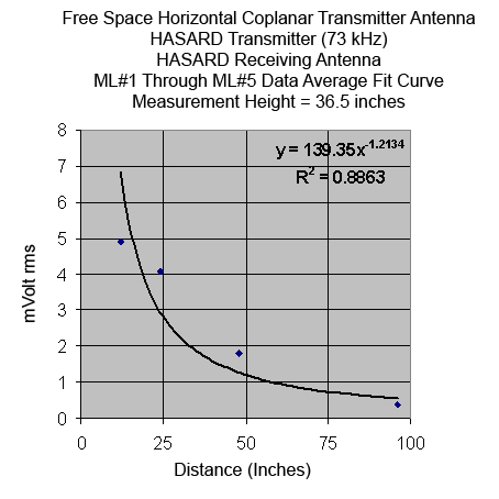
Figure 34
73-kHz magnetic field vs. distance from the rectangular horizontal loop using the HASARD receiver at a height of 36.5 in
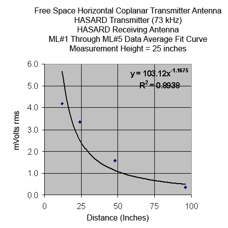
Figure 35
73-kHz magnetic field vs. distance from the rectangular horizontal loop using the HASARD receiver at a height of 25 in
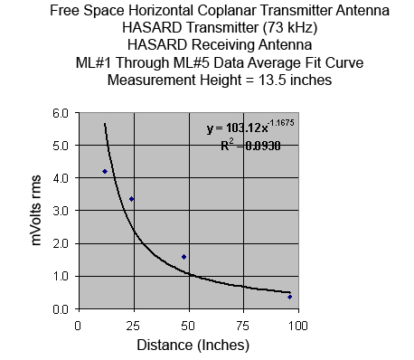
Figure 36
73-kHz magnetic field vs. distance from the rectangular horizontal loop using the HASARD receiver at a height of 13.5 in
The resultant magnetic field measurements done using the HP loop, Holaday 3600, and the HASARD receiver are simultaneously compared for the horizontal coplanar loop antenna at two of the four main heights (namely, 48 in and 13.5 in) and these are shown in Figures 37-38. An example of contour mapping of the magnetic field for a horizontal coplanar loop antenna at a height of 48 in (HT#1) as measured by the HASARD receiver is illustrated in Figure 39. An example of contour mapping of the magnetic field for a horizontal coplanar loop antenna at the 6-ft center point (ML#3) as measured by the HASARD receiver is given in Figure 40.
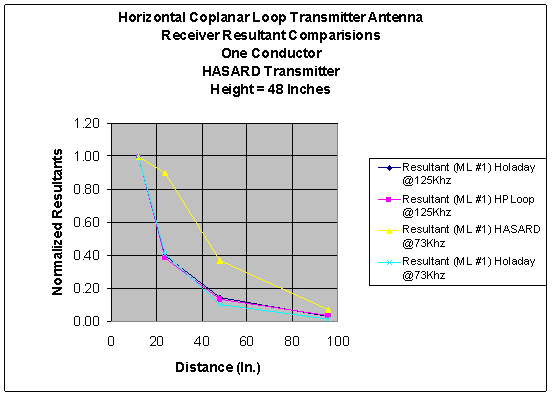
Figure 37
Magnetic field comparisons of the HP loop, Holaday 3600, and the HASARD receiver for the horizontal coplanar loop antenna at a height of 48 in
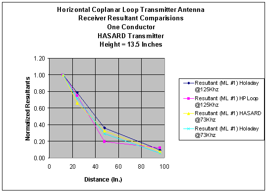
Figure 38
Magnetic field comparisons of the HP loop, Holaday 3600, and the HASARD receiver for the horizontal coplanar loop antenna at a height of 13.5 in
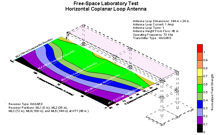
Figure 39
Contour mapping of the magnetic field for a horizontal coplanar loop antenna at a height of 48 in as measured by the HASARD receiver
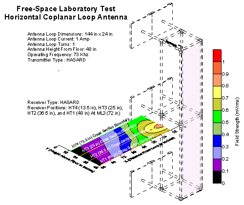
Figure 40
Contour mapping of the magnetic field for a horizontal coplanar loop antenna at the 6-ft center point as measured by the HASARD receiver
Continuous Miner—Wire Loop Antenna Tests
Number of Wire Loop Antennas Required for a Continuous Mining Machine
A considerable amount of effort was focused on determining the number of transmitting wire loop antennas that are needed to generate the necessary magnetic field around a continuous mining machine. Various aspects of this task included determining the impact of loop geometry, loop mounting, and loop protection on the generated field and, in particular, their effect on a constant-field-intensity profile around the machine. It was found that two main loops appear to provide adequate coverage: namely, one large loop around the body of the machine and a smaller loop around the tail/conveyor section.
Effects of Antenna Shielding and Antenna Offset on Signal Strength
HASARD system deployment on a continuous mining machine in a production section of an underground coal mine definitely requires substantial antenna protection as it would always be exposed to tremendous physical abuse. Consequently, a number of laboratory tests were conducted on various types of antenna protection schemes. The first laboratory prototype antenna cover consisted of 1/8-in thick "C" channel with a series of holes in it (Figure 41). The holes allowed the magnetic signal to emanate while providing protection for the wire loop. Figure 42 shows an example of how magnetic field intensity data was collected in the proximity of the mining machine. Experimentation proved that a repeatable and a predictable magnetic field could be developed around the machine with the metal shield covering the wire loop antenna. Figure 43 graphically illustrates how a 1/8 in-thick metal shield over the HASARD wire loop antenna affects the associated magnetic field intensity. Note that this 1/8-in thick shield reduces the measured magnetic field by approximately 50%. Preliminary test results showed the following:
- The received signal strength from insulated (nonconductive) antenna shielding (i.e., PVC pipe) was larger than that from any other conductive antenna shielding materials (e.g., iron, slotted iron, copper).
- The received signal strength for various types of conductive antenna shielding (e.g., iron, slotted iron, copper) were found to be essentially equal.
- For all wire loop antennas, the received signal strength approximately doubled when the antenna was moved from 1 in off the machine frame to 6 in off the machine frame.
Figure 41
Metal shield placed over HASARD wire loop antenna
Figure 42
Collecting magnetic field intensity data associated with shielded wire loop antenna
Figure 43
Effect of metal shield over HASARD wire loop antenna on magnetic field intensity
Magnetic Field Decay as a Function of Distance
Magnetic measurements were taken (using the HASARD resultant voltage output) as a function of distance from the front of the cutting drum of NIOSH's CM. The results correlate well with the basic inverse cube relationship for the decay of the magnetic field (Figure 44). Figure 45 shows the resultant HASARD voltage output as a function of distance from the right side of the CM. The resultant HASARD voltage output as a function of distance from the right side of the tail conveyor of the CM is shown in Figure 46. Again, as expected, the magnetic field decay follows the basic inverse cube trend.
Figure 44
HASARD voltage output as a function of distance from the front of the cutting drum of the CM
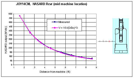
Figure 45
HASARD voltage output as a function of distance from the right side of the CM
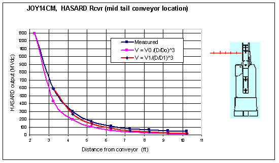
Figure 46
HASARD voltage output as a function of distance from the side of the tail conveyor of the CM
Magnetic Field Contour Plots
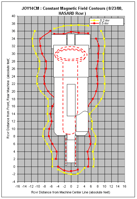
Figure 47
Mapping of the magnetic field at two threshold levels around the perimeter of the CM
The HASARD receiver was mounted on a cart that was slowly moved toward the machine. When the resultant HASARD receiver output reached 0.2 mVdc the cart was stopped and distance to the machine was measured. Likewise, when the receiver output reached 0.5 mVdc the cart was stopped and the distance to the machine was again measured. Mapping of the resultant magnetic field at these two threshold levels (0.2 mV and 0.5 mV) around the perimeter of the CM is shown in Figure 47.
The contour indentation at the operator's cab can probably be attributed to an antenna located behind/under the metal cab roof. Contours along the left side of the machine are not symmetric with those contours on the right side of the machine. A possible cause was thought to be wire mesh in that portion of the floor.
A test was performed to determine if wire mesh in the concrete floor distorted the magnetic field. The machine was moved to an area where wire mesh was known not to exist, and then the antenna was rotated 90°. The receiver was mounted on a cart that was slowly moved toward the machine. When the receiver output reached 0.2 mV and 0.5 mV, the cart was stopped and the distance to the machine was measured. No significant change was observed in the constant magnetic field contour. The cause of distortion appears to be associated with the machine itself.
HASARD receiver output was recorded as the receiver was moved in a vertical plane that extended from 19 in to 55 in above the floor and from 12.5 in to 42.5 in in front of the cutting drum of the CM (Figure 48). The vertical distance mapped was approximately the distance between an average-sized operator's shoulders and knees. Figure 51 shows a side view of the contour lines of the measured magnetic field in front of the cutting drum of the CM. Figure 49 shows contour lines of the measured magnetic field along a portion of the right side of the midsection of the CM. Figure 50 shows a side view of the contour lines of the measured magnetic field adjacent to the right side of the tail conveyor of the CM. The HASARD receiver output was recorded in a 6x16-ft area extending from the midsection to the end of the tail conveyor by moving the receiver in discrete steps at a constant height of 37 in. Figure 51 shows a corresponding top view of the contour lines of the measured magnetic field adjacent to the right side of the tail conveyor of the CM. Figure 52 illustrates a three-dimensional view of the magnetic field around the vicinity of the tail conveyor.
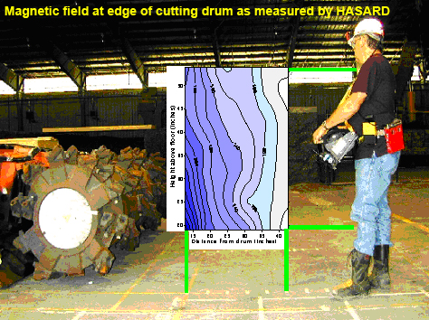
Figure 48
Side view of the contour lines of the measured magnetic field in front of the cutting drum of the CM
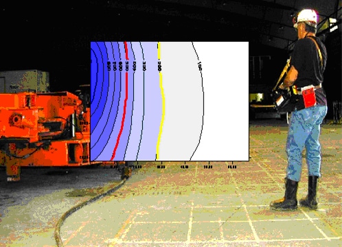
Figure 49
Side view of the contour lines of the measured magnetic field along the right side of the mid portion of the CM
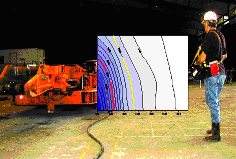
Figure 50
Side view of contour lines of the measured magnetic field along the right side of the tail conveyor of the CM
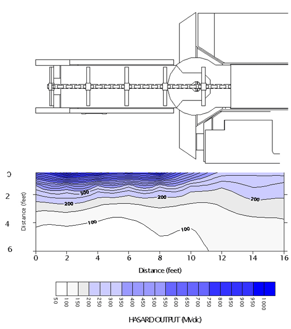
Figure 51
Top view of contour lines of the measured magnetic field along the right side of the tail conveyor of the CM
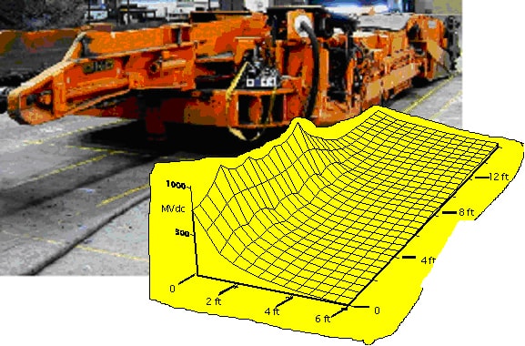
Figure 52
Three-dimensional view of the contour lines of the measured magnetic field along the right side of the tail conveyor of the CM
At two locations (i.e., cutting drum edge and tail conveyor end), a great deal of vertical magnetic field curvature was noted. At the mid tail conveyor location, field curvature became more acceptable; i.e., if alarm trigger points were selected at 0.2 mV and at 0.5 mV, those contours approached vertical straight lines. Also, false triggering of the HASARD receiver was more likely to occur at about 5 ft from the machine.
Effect of Speed on Alarm Trigger Points
To observe the effect of speed on the resultant location of the alarm trigger point from the cutting drum of the CM at two threshold levels (0.195 V and 0.437 V), the HASARD receiver was manually moved at several "constant speeds" of between 0 to 22 in/sec toward the cutting drum of the CM. The results are shown in Figure 53, with the data points shown as small squares. Results show that, at a 0.195-V threshold level at a "zero" speed, the detection distance was approximately 30 in; at a speed of 22 in/s, the detection distance was about 24 in. Likewise, at a 0.437-V threshold level at a "zero" speed, the detection distance was approximately 10 in; at a speed of 22 in/s, the detection distance was about 2 in. In both cases, the graph shows that the detection distance decreases linearly with increasing speed over the range of speeds (0-22 in/s). A similar speed test was then conducted: i.e., moving the HASARD receiver toward the CM at approximate speeds of 3 to 42 in/s on the resultant location of the alarm point from the right side midportion of the CM (Figure 54). Triangle symbols represent data collected beside the operator's cab, and the squares represent data collected by the tail conveyor of the CM. The solid straight lines represent the linear trend line associated with the operator cab, and the dashed lines represent the linear trend line associated with the tail conveyor. At a speed of 3 in/s at the "caution" threshold (about 0.2 V), the detection distance was about 55 in for both the operator's cab and the tail conveyor. When the speed increased to 28 in/s, the detection distance dropped to about 32 in for the operator's cab. When the speed was increased to 42 in/s, the detection distance dropped to 35 in for the tail conveyor. However, at a speed of 3 in/s at the "risk" threshold (about 0.44 V), the detection distance was about 43 in for the tail conveyor and 18 in for the operator's cab. When the speed was increased to 32 in/s, the detection distance dropped to about 25 in for the tail conveyor and remained there for higher speeds (up to 42 in/s). Also, when the speed was increased to 30 in/s for the operator's cab, the detection distance dropped to 5 in. Therefore, to determine the most appropriate safe distances for the "caution" and "risk" zones, one must consider the maximum speed of the machine going toward the worker and, if applicable, the maximum speed of the worker walking toward the machine.
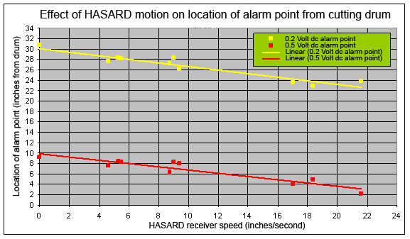
Figure 53
Effect of speed on the resultant location of the alarm point from the cutting drum of the CM
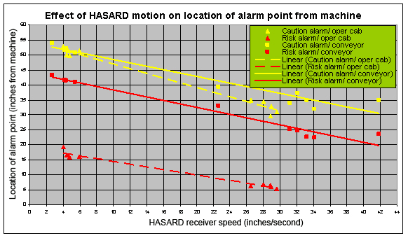
Figure 54
Effect of speed on the resultant location of the alarm point from the right side midportion of the CM
In-house Mine Tests - NIOSH's Safety Research Coal Mine
In-house underground coal mine tests of the HASARD system were conducted at NIOSH's Safety Research Coal Mine at several locations (immediate face area, in a crosscut, and in an entry between crosscuts). The transmitting wire loop antenna was mounted around the perimeter of a Jeffrey 101MC CM as shown in Figure 56. The wire loop antenna is shown as a red line inside the outline of the CM. The entry width ranged from 15.5 ft to 21.6 ft, and the roof height varied from 6 ft to 6.5 ft. In addition to roof bolts at 4-ft spacing, the mine roof was covered with numerous channel straps and wire mesh, each of which could have an effect on the shape and strength of the magnetic field. In this case, magnetic field measurements were taken with the Holaday 3600 VLF survey meter. Figure 57 shows the plot of the resultant magnetic field decaying as a function of distance as measured from the left side of the CM, shown by the blue dashed line in the Figure 58. The basic results learned from these initial in-house underground tests in a coal mine indicated the following:
- The magnetic field intensities decreased as the inverse cube of the distance from the antenna.
- Resonance parameters for the machine-mounted wire loop antenna were different from those when the antenna was free-standing in the entry.
- The wire loop antenna resonance parameters did not appear to change when the machine was moved from mid entry to a crosscut.
- A 3-in antenna offset (distance between the wire loop antenna and machine frame) resulted in an increase in magnetic field intensity. For example, at 2 ft from the cutting drum, the magnetic field increased from 13.2 mA/m at zero offset to 23.7 mA/m at a 3-in offset. The 3-in offset did not change the wire loop antenna resonance parameters.
Figure 55
Location of the CM in NIOSH's Safety Research Coal Mine.
Note: The wire loop antenna is shown as a solid line inside the outline of the CM

Figure 56
Magnetic field decaying as a function of distance as measured from the left side of the CM
Field Tests at a Local Active Underground Coal Mine
An active underground coal mine company near Pittsburgh agreed to provide NIOSH personnel the opportunity to test HASARD in a production environment. A test plan was approved by MSHA and Pennsylvania's Bureau of Deep Mine Safety (BDMS), and each inspected the system after its installation to ensure that it met all applicable regulations. The HASARD tests were primarily designed to determine if the system would be able to survive a typical coal production operation. This mine was a good choice for extreme conditions, due to the type of mining method employed. The coal seam was 12 ft high and had a 6- to 12-in shale parting at 4 ft from the floor. The roof consisted of rock shale. Entries were cut 17 ft wide and curtain ventilation was used.
The mining technique involved first cutting the top 8 ft of coal. Next, the cut would be bolted. Since the mine didn't have a preparation plant, the miners would go back into the cut and take out only the rock parting. The parting would be loaded separately and then used throughout the mine for road bed construction. Finally, the bottom 4 ft of coal for the cut would be mined. During HASARD testing, coal was being mined with extended cuts (37 ft) in an advanced section of the mine. In the HASARD test section, one remote-controlled Joy 12 CM with a ripper cutting head was used with two shuttle cars for haulage.
This particular cutting head had a large and relatively smooth surface. The HASARD wire loop antenna for the cutting head had to be placed on top of this smooth surface. This unique mining method was very destructive to any object that would be attached to the smooth part of the cutting head because the parting would come off in large sheets which in turn would tend to shear off any attached object.
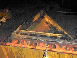
Figure 57
Third underground field test of shielded wire loop antenna mounted on right side of the CM behind the cutting drum
Field Test #1. The HASARD transmitter was bolted close to the center of the continuous mining machine. One wire loop antenna was spot welded to the cutting head and along the conveyor box, down the center of the machine. This antenna consisted of one long cable with two multi-turn lobes encased in a protective metal channel, each attached to the surface of the cutting head.
The second wire loop antenna was spot welded to the conveyor. It consisted of two multi-turn lobes, one on each side of the conveyor. With this configuration, the transmitter was able to generate a magnetic envelope, which extended a number of feet around the periphery of the machine. A receiver was arbitrarily calibrated so that at 2 ft from the machine a "caution" vibratory, audible, and visual signal was triggered and at 1 ft from the machine a "risk" vibratory, audible, and visual signal was triggered. The "risk" signal only provided a response to the miner. The "caution" provided a response to the miner and to a remote alarm/response device. The receiver was worn by a miner operator for a full production shift. The miner's actions were remotely observed, both visually and with a data logger. As the miner moved into and out of the different zones, the indicators on the data logger performed as designed with no major failures. After the tests, the transmitter was removed from the machine, but the antennas were left in place for long-term exposure to production. These first antennas lasted for about one week of production, which consisted of 10 shifts, before being damaged. The antennas on the conveyor were also ripped off.
Field Test #2. More rugged antenna housings were designed and installed. The new cutting head antenna cover was constructed from ¼-in thick angle iron. The conveyor antenna was protected by 1/8-in thick "C" channel. The cutting head antenna was largely encased in the angle iron with some of the cable being attached along the body of the machine. The antenna on the conveyor was recessed into the "C" channel. Again, the system was tested and the antennas were left on the machine. This set of antennas lasted about 1 month. The conveyor antenna suffered minimal damage. One lobe of the cutting head antenna was ripped away, but the second antenna lobe remained intact.
Field Test #3. In the final phase of antenna testing, only a new cutting head antenna housing was evaluated since there was confidence that the 2-in "C" channel would protect the conveyor antenna. The last cutting head antenna cover design consisted of 1/2-in-thick angle iron as seen in Figure 57. A wider weld was used to hold the angle in place more firmly. The cutting head antenna was installed, tested, and left in place for over 3 months. The antenna showed no signs of failure.
After the first two unsuccessful attempts at protecting the wire loop antennas, the third design (½-in thick angle iron) was fully successful. The transmitting antenna on the cutting boom was covered with a metal shield constructed from slotted angle iron (2.75 x 2.75 x 0.5-in thick) and welded to the machine frame. The conveyor antenna was protected by Kindorff channel iron. While these adaptations to the cutting head were temporary for the duration of the tests, they could be permanent fixtures if required. These adaptations were coordinated with the local MSHA inspector.
Results of Field Tests. The signal from the transmitter was degraded each time thicker steel was used for the antennas, but the signal was able to penetrate all the protective coverings and provide a sufficiently large magnetic envelope to identify a hazardous zone. The area in front of the cutter head was the hardest to cover with magnetic signal because the antenna was 2 ft or more from the tip of the picks on the cutter. All other areas around the machine perimeter were easily covered with the signal. A more powerful transmitter and a more finely tuned antenna would certainly achieve a more substantial magnetic envelope beyond the cutter head. Using a higher-power transmitter would probably require housing the transmitter and antennas in explosion-proof enclosures in order to meet the MSHA and Bureau of Deep Mine Safety (BDMS) regulations.
The HASARD transmitting wire loop antennas were intact for a period of 6 months of coal production. The antennas were removed at the conclusion of the tests. Antenna shields can be kept intact during normal coal production. As thicker shields are used, magnetic field intensities will decrease significantly. Also, as the shields become larger, it becomes increasingly difficult to find suitable mounting areas on the machine so that they do not interfere with mining operations.
The HASARD field trials showed the system, if adequately protected, could withstand the abuse of a coal mining production environment. The environment in which it was tested was probably a worst-case scenario due to the unique mining method employed.
Conveyor - In-house Testing
Additional testing of the wire loop antenna configuration was done on a flight conveyor (drag conveyor with bars), which was housed in a high bay of the NIOSH Pittsburgh facility. Figures 58-63 graphically illustrate where the wire loop antenna (as shown by the red line) was mounted around the perimeter of the flight conveyor. The HASARD receiver was rigidly mounted on a mobile positioning platform and set at a height of 56 in, which is the same height as the wire loop antenna that was wrapped around the flight conveyor. A 2-ft X-Y grid spacing pattern was laid out on the floor around the conveyor. HASARD readings at one particular orientation (e.g., X-axis parallel to the wire loop) were then taken at every 2-ft grid point all around the conveyor. Subsequently, HASARD readings in the Y- and Z-orientations were taken, and the resultant voltage values recorded.
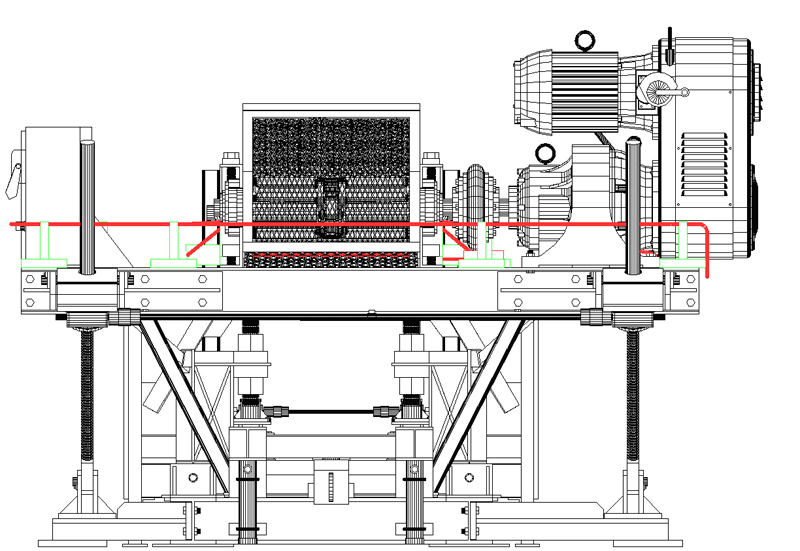
Figure 58
West side of flight conveyor
Note: The red line shows the location of the wire loop antenna
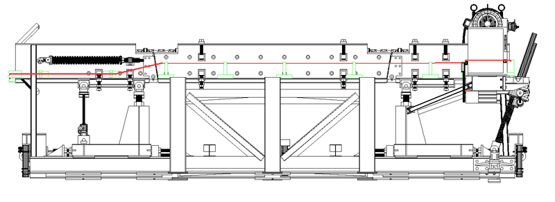
Figure 59
North side of flight conveyor
Note: The red line shows the location of the wire loop antenna
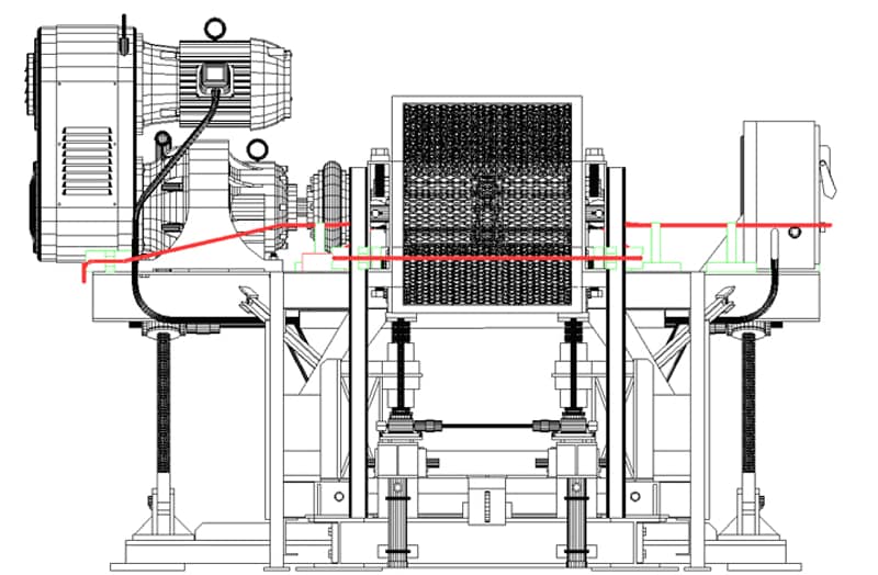
Figure 60
East side of flight conveyor
Note: The red line shows the location of the wire loop antenna
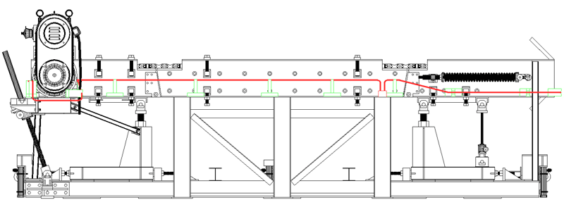
Figure 61
South side of flight conveyor
Note: The red line shows the location of the wire loop antenna

Figure 62
East side of flight conveyor
Note: The red line shows the location of the wire loop antenna along the east and south side of the conveyor. The green lines represent wooden support blocks
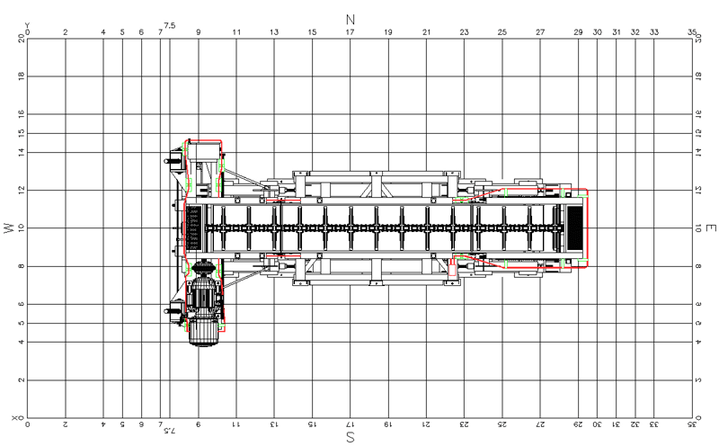
Figure 63
Top view drawing of the flight conveyor
Note: The red line shows the location of the wire loop antenna positioned around the conveyor
The resultant voltages measured by the HASARD receiver at each of three orthogonal orientations (X, Y, Z) are shown in Figures 64-68 at various distances from the north, east, south, and west sides, respectively, of the conveyor.
Figure 68 provides a graphic example of the contour plot of the resultant magnetic field around the flight conveyor with a wire loop antenna mounted around the entire conveyor.
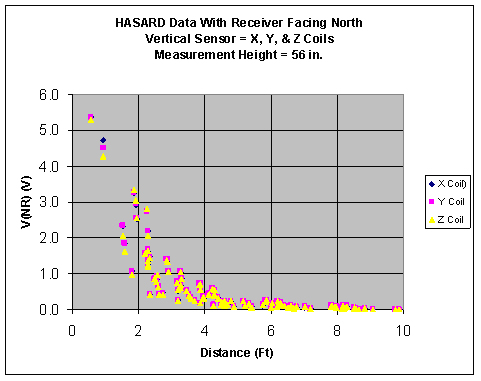
Figure 64
Voltage measurements by the HASARD receiver at three orthogonal orientations at various distances along the north side of the conveyor
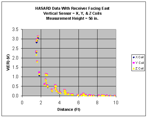
Figure 65
Voltage measurements by the HASARD receiver at three orthogonal orientations at various distances along the east side of the conveyor
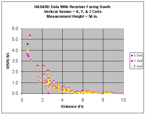
Figure 66
Voltage measurements by the HASARD receiver at three orthogonal orientations at various distances along the south side of the conveyor
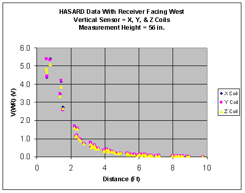
Figure 67
Voltage measurements by the HASARD receiver at three orthogonal orientations at various distances along the west side of the conveyor
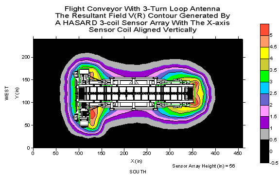
Figure 68
Contour mapping of the magnetic field around the flight conveyor with a wire loop antenna mounted around the entire conveyor
Ferrite Rod Antenna Configuration and Tests
The HASARD wire loop antennas performed well, but installation of the wire loops and on-site calibration (resonant tuning of the transmitter) required a considerable amount of setup time. Special metal shrouds for protection from the environment were also required. In addition, the wire loop antennas tended to have a low efficiency due to low-radiation resistance compared to their dissipation resistance. To alleviate some of the problems, experiments were performed with a ferrite bar-style antenna. Use of a suitable ferrite rod inside of a wire loop can significantly increase the radiation resistance and also has the effect of intensifying the magnetic field inside the loop. This is produced by the high permeability of the ferrite material. Hence, the ferrite rod can have a dramatic effect in improving the antenna's efficiency in gain and effective area, resulting in a great improvement in the size of the loop to the size of the generated magnetic field ratio. The ferrite antennas can be much smaller while still generating a reasonably sized magnetic footprint compared to a given wire loop. They can also be tuned prior to installation, since the field is contained around the ferrite rod and not around the metal mass of the machine. One or more ferrite rods can be placed around the machine to obtain the desired coverage area.
Continuous Miner
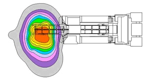
Figure 69
Contour mapping of HASARD-generated magnetic field, with the pipe antenna mounted on the right side of the tail conveyor
Preliminary surface trials of the HASARD system using the ferrite rod antennas were performed on the Joy 14 CM at Pittsburgh. The primary objective of the test was to determine the "footprint" of the magnetic field generated by the HASARD transmitter and ferrite rod antenna. The ferrite rod antenna was mounted on the midsection of the tail conveyor, about 42 in from the back end of the mining machine and at a height of about 48 in above the ground. The HASARD transmitter current was set to 1.0 A. All data was taken with the NIOSH-built HASARD receiver. The position for each measurement was determined by using a round, metal protractor-style plate, placed on the top of a tripod. The metal plate was etched at 10º increments. An auto-leveling, laser-ranging device was placed on the center of the plate. Two of three laser beams provided by the auto-leveling laser were used. The laser beams were generated at 90° to one another. One laser beam indicated the angle of the measurement with reference to the machine, and the second laser beam was projected to the case of the HASARD receiver. A rope knotted (marked) at 2-ft increments provided a distance measurement from the center radials. Magnetic field signal strengths were indicated by a DC voltage in the range of 0-5 V. In most cases the data were taken at 10º and 2-foot increments out to a distance of 12 ft. Figure 69 shows the top view of the contour plot of the HASARD-generated magnetic field, with the ferrite rod antenna mounted on the right side of the tail conveyor. Initial data analysis indicated that the magnetic field produced by the HASARD transmitter appears to be reasonable and practical for underground use. As can be seen in the magnetic field plot (Figure 74), the magnetic field is not necessarily regular in shape. Consequently, for this system to be a safety-based system, one needs to find the lowest voltage when going around the entire circumference (0°-360°) at a given distance from the HASARD antenna and use that as the required threshold level. It should be noted that users must always comply with all MSHA rules and recommendations regarding keeping miners outside of any "red zones" (e.g., Red Zones are No Zones for Mining With Remote Control CMs [MSHA 2004]).
Conveyor - In-house Testing
Figure 70 is a plot of the resultant elliptically shaped magnetic field for the ferrite rod antenna positioned horizontally in free space. Five different constant currents, ranging from about 0.12 to 1.37 A, were applied to the antenna. At a current of 0.125 A, the signal was detected at about 39 in (ranged from 36-42 in). At a maximum current of 1.37 A, the signal was detected at approximately 100 in (ranged from 89-113 in).
Figure 71 gives a plot of the resultant circular-shaped magnetic field for the ferrite rod antenna, positioned vertically in free space. Five different constant currents, ranging from about 0.12 to 1.37 A, were applied to the antenna. At a current of 0.125 A, the signal was detected at about 34 in (ranged from 30-36 in). At a maximum current of 1.37 A, the signal was detected at approximately 90 in (ranged from 88-95 in).
Figure 72 provides a plot of the resultant magnetic field for the ferrite rod antenna mounted horizontally and parallel on the south side of the flight conveyor. The antenna was mounted at three different distances (1 in, 3 in, and 6 in) from the conveyor.
Figure 73 shows a plot of the resultant magnetic field for the ferrite rod antenna mounted horizontally and perpendicular on the south side of the flight conveyor. The antenna was mounted at three different distances (1 in, 6 in, and 12 in) from the conveyor.
Figure 74 gives a plot of the resultant magnetic field for the ferrite rod antenna mounted vertically on the south side of the flight conveyor. In this case the antenna was mounted at two different distances from the conveyor.
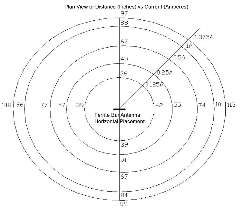
Figure 70
Plot of the magnetic field for the ferrite bar antenna positioned horizontally in free space for five different currents
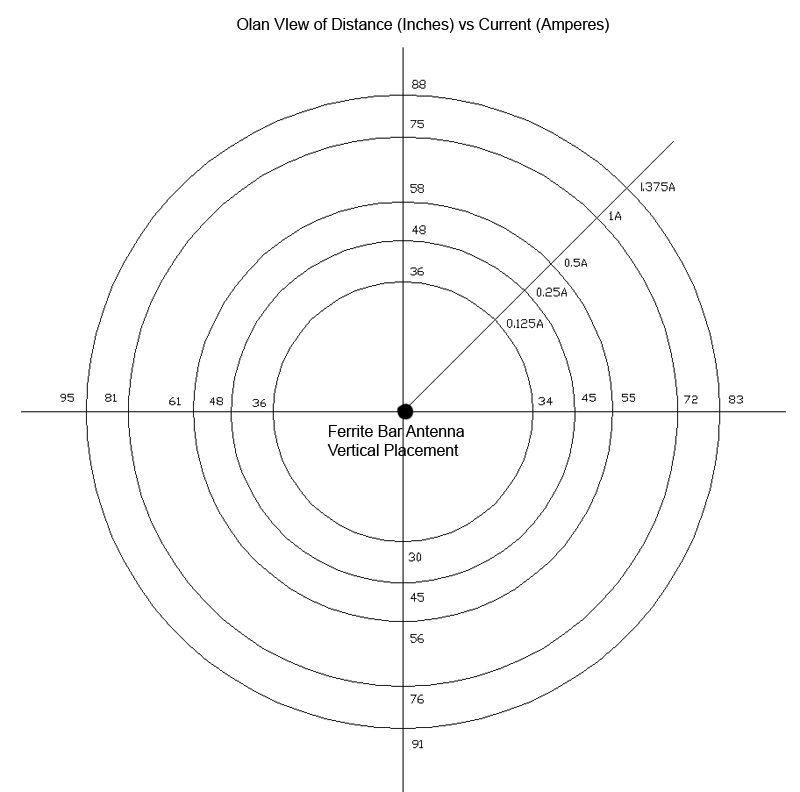
Figure 71
Plot of the magnetic field for the ferrite bar antenna positioned vertically in free space for five different currents
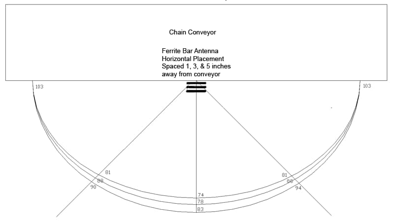
Figure 72
Plot of the magnetic field for the ferrite bar antenna mounted horizontally and parallel on the south side of the flight conveyor at three different distances from the conveyor
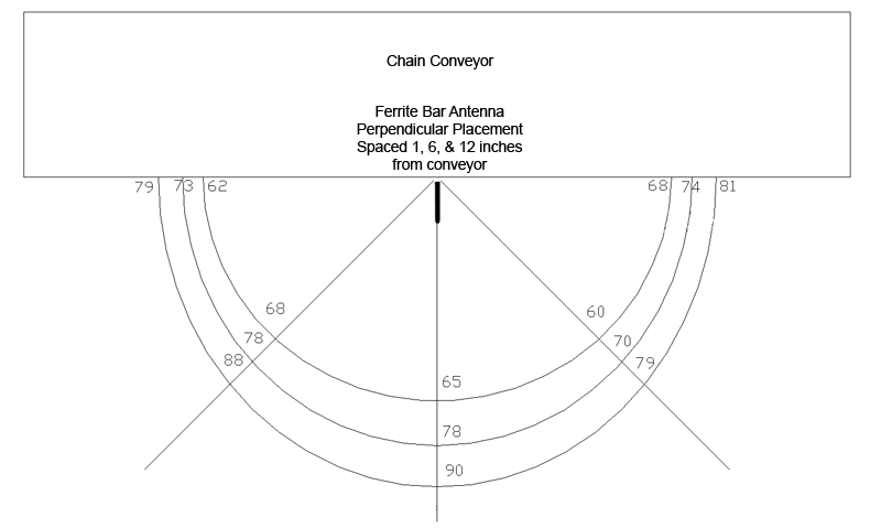
Figure 73
Plot of the magnetic field for the ferrite bar antenna mounted horizontally and perpendicular on the south side of the flight conveyor at three different distances from the conveyor
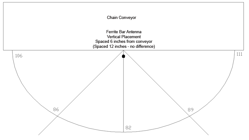
Figure 74
Plot of the magnetic field for the ferrite bar antenna mounted vertically on the south side of the flight conveyor at two different distances from the conveyor
Field Test at a Quarry
The purpose of this field test was to install the prototype HASARD system on a moving conveyor where workers sometimes travel at an active quarry operation, collect HASARD-generated magnetic field strength data, and analyze and prepare magnetic field strength plots of the collected data. A nearby limestone quarry and processing plant was selected as the test site due to the fact that it was relatively close to NIOSH Pittsburgh.
HASARD Setup
Figure 75 shows an overview of the conveyor, crusher, and other associated equipment. The HASARD system was set up by first magnetically mounting the ferrite rod antenna along the base of the conveyor support as shown in Figure 76. Two magnetic fastening disks were used to secure this antenna to the conveyor support.
The HASARD transmitter, a 12-V car battery power supply, and a battery-powered oscilloscope (Tektronix THS 720A) were situated at the bottom of a catwalk, directly beside the conveyor. An umbrella was used to help protect the equipment from the rain, which was intermittently falling during the testing phase. A laser level with a protractor template, for establishing angles at 10° increments, was positioned directly under the HASARD antenna (Figure 77). A calibrated rope, marked off in 2-ft increments, was used to determine distances from the laser level and the HASARD antenna.
Power Spectral Plots—Electromagnetic Background Noise
After the HASARD transmitter and antenna system were installed adjacent to the conveyor and the transmitter current was adjusted to an output of 1.0 A (4.0 Vrms as measured across a 4-Ω resistor), power spectral plots were made using a small ferrite bobbin connected to a portable spectrum analyzer (Hewlett Packard HP8561B). Electromagnetic background noise data was collected directly beside the ferrite rod antenna, then 3 ft away, and then 6 ft away from the antenna (Figure 78).
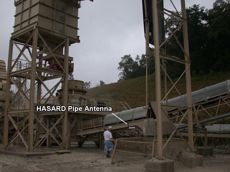
Figure 75
Overview of the area around the HASARD pipe antenna
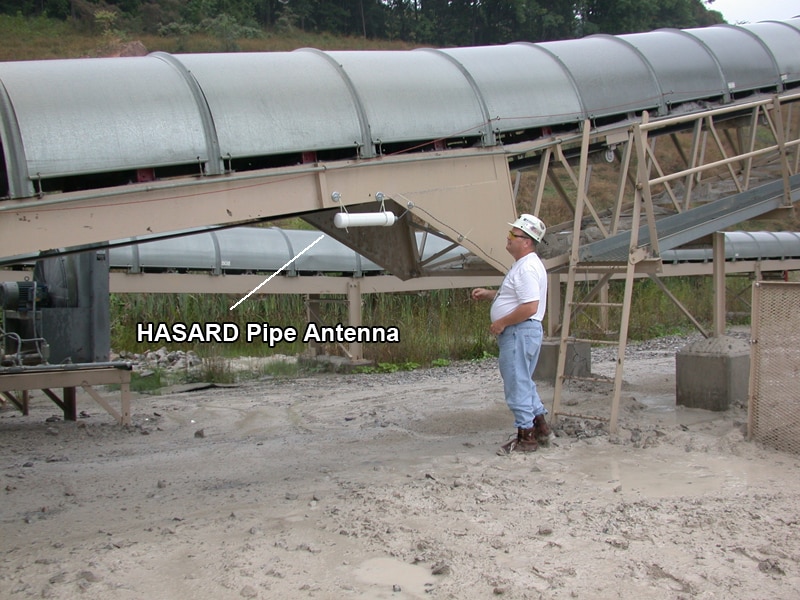
Figure 76
HASARD pipe antenna mounted under the conveyor
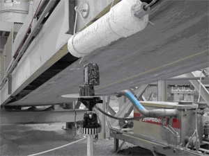
Figure 77
HASARD pipe antenna and laser level directly beside the conveyor
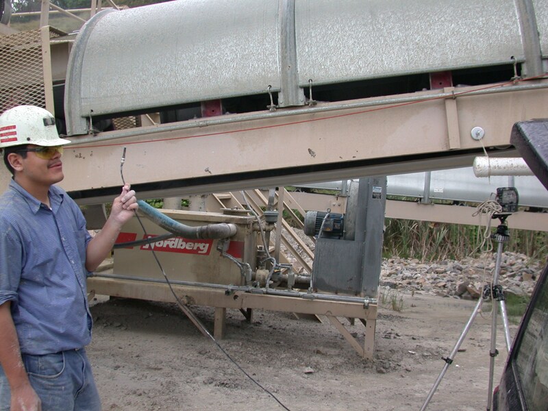
Figure 78
Power spectral electromagnetic noise measurements being taken around the HASARD pipe antenna
Figures 79 and 80 show how the peak spectra at 73 kHz dropped as the ferrite bobbin was moved away from the HASARD ferrite rod antenna and also that the background noise with the conveyor and associated equipment running (5-100 kHz) was essentially constant and well below the 73-kHz signal level of the HASARD transmitter. This indicated that the HASARD system could be used at this location without having to change its operating frequency.
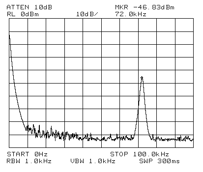
Figure 79
Power spectra measured directly beside pipe antenna
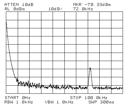
Figure 80
Power spectra measured at 3 ft away from the pipe antenna
HASARD Data Collection
HASARD magnetic field strength data was collected using a HASARD receiver at two different heights: 4 ft above ground (2 ft below the pipe antenna) and 2 ft above ground (4 ft below the ferrite rod antenna). The HASARD receiver measured each orthogonal component of the magnetic signal, squared each component, and then took the square root of the sum of the squared readings in order to compute the resultant magnetic field strength value.
Readings of the resultant magnetic field were taken every 10º (from 0° to 360°) at 2-ft increments from 2 ft to 12 ft. The 0º starting point was referenced to the wire coming out of the ferrite rod antenna. The ferrite rod antenna was oriented parallel to the conveyor, with the antenna power wire positioned at the upward slope direction of the conveyor. The conveyor was running continuously during the data collection. Data was manually entered into a field notebook. Over 400 data points were recorded in a polar coordinate format (i.e., measurement height, angle, and distance from antenna).
Two sets of HASARD magnetic field strength readings were collected:
- Data Set #1: 4 ft above ground, 2 ft below pipe antenna (Appendix A, Table A-1)
- Data Set #2: 2 ft above ground, 4 ft below pipe antenna (Appendix A, Table A-2)
Mapping of HASARD Results
After the test, the manually collected data points (polar coordinates) were entered into an Excel spreadsheet and then converted into rectangular coordinates. The resultant data was next converted into contour plots using the software program Surfer v8 (Golden Software).
The contour plots show contour lines of equipotential voltage (i.e., magnetic field strength) around a localized X-Y coordinate grid at a given height above the ground (i.e., distance below the ferrite rod antenna). This information was used to help define the appropriate voltage threshold level(s) for setting off an alarm to the worker. In Figure 81, at a height of 2 ft above ground (4 ft below the ferrite rod antenna), the 0.5-V threshold is represented by an approximate 20x16-ft oval. The 3.0-V threshold is represented by an approximate 4x5-ft oval. In Figure 82, at a height of 4 ft above ground (2 ft below the ferrite rod antenna), the 0.5-V threshold is represented by an approximate 20x16-ft irregular oval, somewhat similar to that of Figure 86. At the 3.0-V threshold, an irregular circle about 12x12 ft can be seen.

Figure 81
Contour mapping of HASARD data taken at 2 ft above the ground, 4 ft below the pipe antenna
Note: The conveyor is shown as a translucent gray-shaded horizontal bar across the middle of the plot
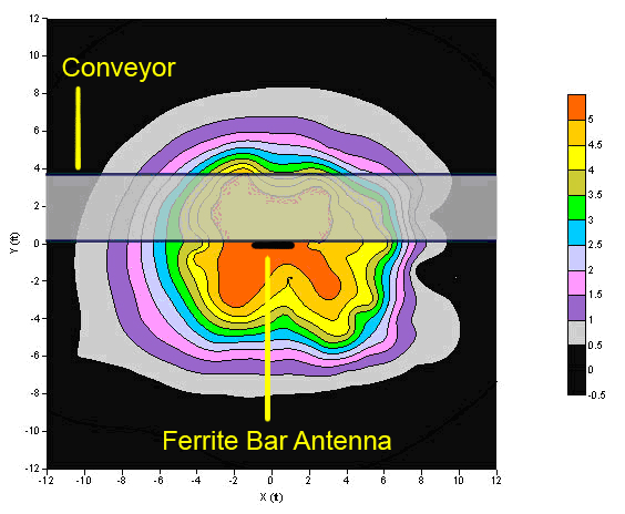
Figure 82
Contour mapping of HASARD data taken at 4 ft above the ground, 2 ft below the pipe antenna
Note: The conveyor is shown as a translucent gray-shaded horizontal bar across the middle of the plot
HASARD Test Summary - Conveyor
The prototype HASARD system using the ferrite rod antenna was temporarily installed on one side of a moving conveyor belt at an active limestone quarry and processing plant in southwestern PA. The main objectives of this trip were accomplished and included (1) measuring the ambient electromagnetic noise spectra during normal conveying operations, (2) collecting magnetic field strength data around all sides of the conveyor, and (3) mapping the resultant magnetic field generated by the HASARD transmitting ferrite rod antenna. Initial data analysis results indicated that the HASARD operating frequency was well above the ambient electromagnetic noise and consequently would not be affected by electromagnetic noises being generated by the moving conveyor belt or other supporting equipment (e.g., motors, rock crusher). Approximately 400 magnetic field strength readings (from 2 to 12 ft away, at 10° increments) were taken with the HASARD receiver at two different heights below the HASARD ferrite rod antenna, and representative magnetic field strength plots were prepared (Figures 81 and 82).
Haul Truck Field Test
HASARD Setup
The HASARD transmitter ferrite rod antenna was installed, using mounting magnets, on the back of a 10-ton International C1640 haul truck at Pittsburgh as shown in Figure 83. The ferrite rod antenna was used on the truck due to the ease of installation as compared with attaching a wire loop around the perimeter of the truck body. Also, the ferrite rod antenna did not need to be calibrated in the field as it had already been calibrated in the laboratory. In contrast, a wire loop antenna would need to be calibrated once it was installed on the truck because of the close coupling to the metallic structure of the truck, which detunes the antenna. A laser level, protractor template, tripod, and calibrated measurement rope were used to obtain the measurements. A close-up view of the installed ferrite rod antenna, laser level, and protractor template is shown in Figure 84.
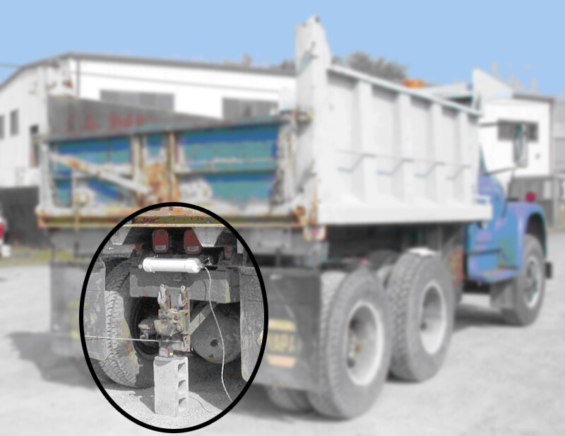
Figure 83
HASARD pipe antenna installed on rear of 10-ton haul truck
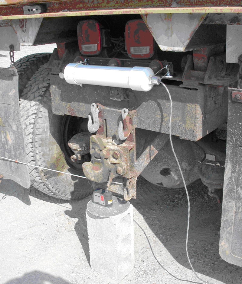
Figure 84
HASARD pipe antenna, laser level device, and protractor template installed on rear of 10-ton haul truck
HASARD Data Collection
HASARD magnetic field strength readings were taken every 10° increments (total 360° coverage) at every 2-ft radius increments (out to a distance of 12-14 ft) (Figure 85). The reference point was the center of the back of the truck, where the HASARD ferrite rod antenna was installed. The 0° reference angle was where the wire exited the ferrite rod antenna, with the angular measurements going clockwise from this point. The HASARD transmitter current was set at 1 A. The data points were manually entered into a field notebook.
Three sets of HASARD magnetic field strength readings were collected:
- Data Set #1: Constant height of 2 ft with truck bed down (Appendix B, Table B-1)
- Data Set #2: Constant height of 4 ft with truck bed down (Figure 83; Appendix B, Table B-2)
- Data Set #3: Constant height of 4 ft with truck bed up (Figure 87; Appendix B, Table B-3)
Mapping of HASARD Results
After the tests, the manually collected data points (polar coordinates) were entered into an Excel spreadsheet and then converted into rectangular coordinates. The resultant data was next converted into contour plots using the software program Surfer v8 (Golden Software). The worker protective halos were slightly elliptical in all three cases (Figures 86 and 88). Appendix B gives the magnetic field strength (as measured in volts) for the three sets of data.
HASARD Test Summary on Haul Truck
Using the ferrite rod antenna, the HASARD system was found to provide a consistent safety marker around the back and two sides of the haul truck, independent of the position of the truck bed as shown in Figures 86 and 88. For a transmitter current of 1.0 A, the complete back portion of the truck (8 ft across and 3 ft directly behind) had a measured value of at least 4.5 V. At a voltage threshold of 0.5 V, the magnetic markers were about 7 ft behind the truck and about 10 ft on either side of the truck. Increasing the transmitter current (a simple procedure, but only provides a small increased benefit) and/or increasing the sensitivity of the HASARD receiver (the preferred adjustment, but which should be done in the laboratory) will increase the size of the magnetic markers, if required.
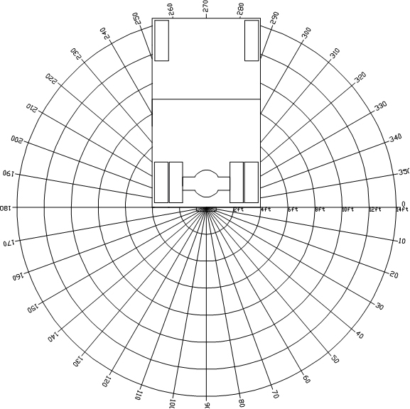
Figure 85
Data collection layout on the 10-ton haul truck
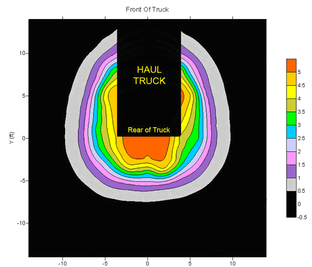
Figure 86
Contour mapping of HASARD-generated magnetic field, with readings taken at a height of 4 ft above the ground, with the truck bed down

Figure 87
HASARD readings taken at a height of 4 ft, with the truck be up
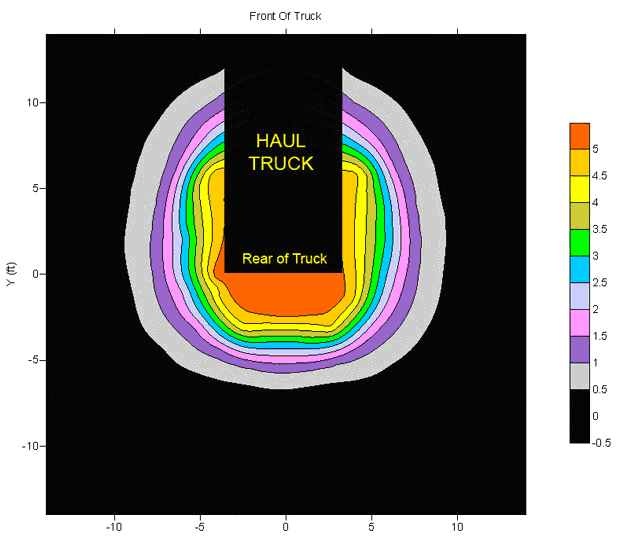
Figure 88
Contour mapping of HASARD-generated magnetic field, with readings taken at a height of 4 ft above the ground, with the truck bed up
Recommendations and Enhancements - HASARD System
General Considerations
A few enhancements to the basic HASARD design could help improve system functionality, performance, and safety:
- Calibration and testing procedures to verify that the HASARD transmitter, wire loop antennas, receivers, and warning devices are all functioning properly.
- MSHA-approved "explosion proof" box to contain the transmitter, hence the output of the HASARD transmitter (and the range of the system) could be substantially increased.
- Portable HASARD test receiver with visual display to indicate the strength of the magnetic field provided by the transmitter and antenna for calibration and troubleshooting.
- HASARD receiver residing on the machine to ensure that a certain level of signal is received a certain distance away from the HASARD transmitter. Any signal loss would trigger an alarm. This would effectively test the power source, the transmitter power output, and the antenna integrity.
- A smaller design for the device so that it could be used on a miner's cap lamp or on a remote-controlled pendent for the CM.
- HASARD receiver battery level circuitry could provide an alert should the battery power drop below a useable level.
- Black-box data logging (e.g., remaining battery life and HASARD receiver time-of-entry into a zone, time-of-exit out of a zone, ID, and distance to the CM) and archiving the information to the base station.
Haul Truck Considerations
A few considerations pertaining to the haul truck could help improve system functionality, performance, and safety:
- Narrower detection zone on the sides of the haul truck. With the current HASARD system, the detection zone along the side of the truck is too wide.
- Alarms activated only when the truck is in reverse.
- Different alarm zones with a different alarm sound for each zone (e.g., continuous-tone alarm at 0-5 ft from the rear of the truck, fast-pulse alarm at 5-10 ft, and slow-pulse alarm at 10-15 ft).
- Alarm interface in the truck cab, compact in size with a power indication light.
- Intuitive lamp display (i.e., series of LED's that light in succession as the man-to-machine distance decreases).
General Concerns
The main goal and benefit of HASARD is to warn CM operators and helpers when they are too close to the equipment. The benefit depends upon the acceptance of the system by both users and mine management. The advantages of this system outweigh the disadvantages, provided that the system is implemented appropriately.
CM operators and helpers are constantly challenged by the dynamic work environment in which they work. They make decisions that include aspects of production, planning, geology, and equipment. These decisions are based on miners' awareness of the current mining conditions and their coworkers. Although they are concerned with personal safety, operators and helpers tend to focus mainly on the extraction of coal and the conditions of the face area of the mine. A device that warns them when they have positioned themselves within a danger zone of the equipment could help relieve operators of the safety aspect of the mining process. If operators are able to rely on a PW system, it could help free up some of their attention to concentrate on other aspects of the work environment. This HASARD device may keep the operator further from the equipment and the dangers associated with operating close to equipment and mine ribs. The system could also be used to train new CM operators on how to operate equipment from a further vantage point than CM operators traditionally operate.
HASARD is designed to stop the machine when the operator gets into a pinch point; it will reduce "struck by" and "caught between" accidents in continuous mining operations. Once an operator decides to trust the system and lets the system tell him/her when they are in a pinch point area, then the system must not fail. Failsafe design is essential and proper notification of when the system is not working should be integrated.
When the system may get in the way, the operator may try to override it. For instance, during maintenance, it is necessary for operators to get close to the machinery. In the past, crushing accidents have occurred when maintenance personnel were testing appendages while the power was on at the machine. The appendage would trap the maintenance personnel between two parts of the machine or between the machine and the rib. A lock-out/tag-out approach, where the maintenance personnel can only maintain the machinery if all power is shut off, should be applied.
Since mine geology, ventilation, equipment, miner operator preferences, and mine plans are unique to each mine, the HASARD or alternative PW system would have to be customized and calibrated at each mining site. Determining proper and safe warning distances is necessary to ensure the system would be beneficial to the user. In addition, training for calibration, customization, installation, and maintenance of the system must be provided to the miners.
HASARD receivers should be placed on all workers at the face area. Not only the operator and helper, but all workers in the vicinity of the CM could be crushed or hit by machinery. Therefore, all workers should have the benefit of an automatic warning if they are too close to the equipment.
Electromagnetic Field—Human Exposure Level
Any electromagnetic field (EMF)-based safety system should comply with permissible exposure levels and exposure times. Some of the dosimetric parameters include current density, specific energy absorption rate, and specific energy absorption. Exposure time parameters in relation to time-varying fields used in specifying exposure limits include electric field strength (E, measured in V/m), magnetic field strength (H, measured in A/m), and magnetic flux density (B, measured in Teslas). Alternating current (AC) fields induce electric currents in conducting objects, including humans; DC fields do not induce currents unless the DC field changes in space or time relative to the person in the field. Induced currents from AC fields have been the focus of research on how an EMF could affect human health. An EMF is a composite of electric and magnetic fields, each having different properties and possibly different ways of causing biological effects. Both electric and magnetic fields weaken with increasing distance from the source. The HASARD marker is the magnetic field. The HASARD transmitter is designed to develop a maximum of 1.5 A into a 4-Ω resistive load, which is the maximum output the transmitter could develop in any type of load. The normal load on the HASARD transmitter will be one or more loop antennas or one or more ferrite rod antennas. Both antenna types can be considered loop types in that they use multiple turns of wire. Typically, the wire loop will be three turns or less, and the maximum size of a loop will be about 2.5x7 m. The ferrite rod antenna will generally consist of eight turns or less with a maximum length of 12 in and a maximum width of 1 in.
The Biot-Savart Law relates magnetic fields to currents and can be used to determine the magnetic field generated. The law states that a single-turn, circular loop with a diameter of 1 m will generate a magnetic field at its geometric center equal to the loop current. Consequently, a round, 1-m diameter loop carrying 1 A of current with one loop will produce a field of 1 A/m at its center. A two-turn loop will produce 2 A/m, and a single-turn loop with 2 A of current will also produce 2 A/m. Large pieces of metal, such as a CM, cause the magnetic field to decrease in magnitude. In practice, it is easier to install the system on a CM and then measure the resulting fields. With HASARD, using a two-loop configuration (both machine body wire loop antenna and conveyor wire loop antenna in operation), spot measurements were made around the NIOSH CM (a Joy 14CM) to determine magnetic field human exposure levels using a radiation survey meter (Holaday Industries HI-3600). With transmitter currents set to trigger an arbitrary user-defined typical "risk" zone (transmitter current set for each wire loop antenna to give a resultant voltage reading of 0.5 V at a distance of 42 in from the machine), the magnetic field was found to be less than 5 mA/m (rms vector magnitude) at 18 in from the machine. This is well below the American National Standards Institute (ANSI) 1.63 A/m safety level standard (3-100 kHz band, ANSI/Institute of Electrical and Electronic Engineers (IEEE) C95.1-1991) and the United States Air Force (USAF)1.63 A/m standard (10 kHz to 3 MHz band, USAF, 1987) for human exposure to electromagnetic fields.
Technical Considerations
A few technical considerations should be addressed when implementing an active-type, EMF-based PW system such as HASARD:
- Magnetic field envelope. The magnetic field envelope should be well defined and should be mapped with a calibrated receiver to insure that its footprint accurately covers all the desired areas of protection.
- Scheduled testing and calibration. Periodic checks should be made to ensure that the magnetic field is as intended. A machine-mounted receiver could also provide a continuous integrity check of the magnetic field envelope.
- Performance near radio reflective environments. LF magnetic field signals, such as those used by HASARD, are minimally affected by the environment. Medium frequency and higher signals can be significantly affected by metal, wires, rough surfaces, smooth surfaces, water, dust, etc.
- Susceptibility to conducted and radiated EMF interference. Any high-level electrical signal in the vicinity of the PW system should be a concern, particularly a signal that is within the frequency of operation. A scan of the area in which the system will be used should be conducted with a spectrum analyzer to determine if there is cause for concern.
- Orientation sensitivity. EMF-based receivers can have high orientation sensitivities, especially if the source of the signal being received is from a loop-type antenna. The HASARD receiver compensates for this problem by providing orthogonal receiver antennas on three axes.
- Response time. This parameter deals with the time the receiver enters a marker zone and when the receiver and/or base station provides an alert or machine shut down. Factors such as machine speed and system response time need to be determined.
- Electromagnetic compatibility. The device, equipment, or system should be able to function satisfactorily in its electromagnetic environment without introducing intolerable electromagnetic disturbances to anything in that environment. This issue is addressed in American National Standard for Electromagnetic, Compatibility Limits—Recommended Practice, ANSI (C63.12-1999).
- IS/XP requirements. If the PW system will be used in the return area of an underground coal mine, then either intrinsically safe (IS) or explosion proof (XP) design criteria must be incorporated. In the case of HASARD, the prototype system was designed to be IS. The HASARD system received an MSHA experimental permit as well as Pennsylvania Department of Environmental Protection BDMS permit before in-mine testing was conducted. Pursuit of a permit in compliance with either standard can be time consuming and expensive.
- Blasting safety. If blasting caps are being used, the EMF of the PW system must be taken into consideration so that it will not cause a blasting cap to initiate [IME 2001].
Implementation Impact
After technical effectiveness of the HASARD system has been established, proper usability testing is necessary. Too many times systems or processes are put into an environment without determining the possible introduction of new risks to users and how users might misuse the system. End users of a system can provide important feedback to better evaluate current and proposed designs leading to safer and more effective use of proposed systems. When new technology is introduced into a system, accidents may occur if human-system interactions were not considered adequately in the design process. These are known as unintended consequences. For example, the implementation of extended-cut mining using remote-control technologies was introduced in the 1990s and was being used without proper regard to the human component of the system. Remote-control technology was introduced to provide a safer and more efficient mining environment. Consequently, machine operators were no longer required to be on the equipment and could now position themselves back and behind the machine. Previous cutting procedures had the operator riding on the deck of the machine. Remote-control technology has also provided a way for mines to take longer lengths of cuts, thus increasing production and leading to widespread adoption. Once remote-control technology began to be widely used, new issues became evident. The operator could move about the area instead of being in the compartment and, consequently, could be hit by machinery, have increased exposure to roof and rib falls, and have different visibility from the new vantage points.
The introduction of any new technology to an existing piece of equipment may cause procedural changes in the way the equipment is operated. These changes have the potential to create new hazards to the operators of this equipment. The industry must be made aware of this potential and should be provided with information, training, and assistance to ensure the introduction of a PW system provides the intended result—improved safety of machine operators and their coworkers.
Human Factors Perspective
Designers of HASARD and other PW systems are not only faced with technical equipment operation criteria, but also with the integration of sound human factors principles and recent human factors research.
Studies of operator positioning around remote control mining sections have been collected by NIOSH ergonomics personnel [Steiner 2002; Zeiler 2006; Burgess-Limerick and Steiner 2006]. All of the data helps to make informed decisions about where miners should be positioned. After implementation of a new system, the habits of operators/helpers should be carefully studied—first, without the operator's knowledge of the system and, second, after operators are trained as to how the system functions and are given warning signals as feedback of their positioning. Observations, open-ended interviews with CM operators and management, and time-coded positioning data via a data logger should be collected. The results determine the system/equipment/personnel functions of the PW system and help to determine what design and implementation inadequacies may need to be rectified. Test results would help to establish requirements for changes to training and procedures. Moreover, such studies would help fine tune the system as well as predict how the operator may rely on the system and how it will change the way the operator mines coal.
Several critical questions should be addressed when studying PW systems:
- Does the PW system cause the CM operator (or helper) to move to or to spend more time in a position of safety?
- Does the PW system cause the operator (or helper) to move to and operate from locations that are less safe or safer than were used without the system. This question can be answered by analyzing the time spent in each zone both before and after the operator is aware of the system.
- Are the light-based warning devices discernable (e.g., red and amber) and appropriate (e.g., color, signal, and timing)? The signals must be discernable, appropriate, and not cause excessive reaction. Researchers will be able to tell if the lights are effective by the response/reaction time when the "caution" and "risk" zones have been violated.
- Are audible alarms loud enough over machine noise to be heard with earplugs? Post-study interview questions should help in providing answers to such questions.
- Does the PW system cause operators to react adversely to the warning signals (in terms of operator positioning)?
- Does the PW system cause the operators to respond adversely? The device may force the operator to operate from a very different vantage point (e.g., operating the machine from the other side), one with which he/she is not familiar. The operator may choose to move closer to the rib which can be dangerous if the rib is not in good condition. Operators habits before (baseline) and after awareness of the device will tell safety and ergonomics personnel if the device made the operators respond adversely.
- Are there situations where the PW device may cause additional safety or health concerns (unanticipated consequences)?
- Does it appear that the operator can rely on the PW system?
HASARD Application Synopsis
As previously described, NIOSH tested the HASARD prototype technology in laboratory and field settings with remote-controlled continuous mining machines, shuttle cars, conveyor belts, and haul trucks. The HASARD concept was initially adopted by Geosteering, which developed it into a product for use on continuous mining machines under the product name of TramGuard®. Frederick Mining Controls then further developed HAZARD into a product called HazardAvert® which is presently used on highway construction haul trucks, surface mining haul trucks, and forklifts. Frederick Mining Controls demonstrated its use on CMs and shuttle cars in a SASOL mine in South Africa in January 2009. Matrix Design Group (Alliance Coal) used the HASARD concept to develop a product called the Matrix Miner Monitor M3-1000, designed for use on remote-controlled continuous mining machines in which the miners carry transmitters and the machine has four strategically placed receivers. ICG Addcar used the HASARD concept on a product they developed for use on conveyor belts on their highwall mining systems. A number of other companies have applied HASARD to equipment and vehicles in ship yards, steel-making plants, and other industrial settings.
Conclusions
NIOSH researchers designed, tested, constructed, and evaluated a prototype PW system called HASARD, which could be used to warn mine workers whenever they get too close to a remote-controlled continuous mining machine.
The prototype HASARD system provided a number of distinct attributes:
- Preliminary testing indicated that the HASARD system was reliable in underground mining environments.
- Being an active system, only miners who carried a HASARD receiver could cause the system to go into the alarm state.
- HASARD system calibration was simple.
- HASARD was ideal for "close proximity" sensing applications.
- The HASARD receivers were relatively small overall and light weight; use of surface-mount technology could make them even smaller.
- A wire loop antenna could be used to contour a magnetic field around large and/or complex-shaped objects such as a conveyor belt or large piece of irregularly shaped machinery.
- A ferrite bar antenna could be used when providing localized concentrated zone protection on continuous mining machines, haul trucks, and other mining and construction vehicles.
- The HASARD system was granted an experimental permit by MSHA and was found acceptable for use in underground coal mines in Pennsylvania by the Pennsylvania DEP, BDMS.
- The HASARD technology was patented and is now available for licensing (see "Patent and Licensing Information" section below).
Limited field trials of HASARD showed that the system could survive in a very harsh industrial environment provided that it was adequately protected. The most vulnerable part of the system was the wire loop antenna. The wire loop antenna used in the underground field trials (protected by 0.5-in-thick steel channel) was still found to be in excellent working condition after 6 months of active coal production.
In summary, the HASARD PW system provides a robust, consistent magnetic field which can envelop an area around a piece of equipment or a vehicle that has been deemed potentially dangerous. The HASARD system has many potential safety applications for warning and protecting personnel working in close proximity to potentially dangerous areas around many different work environments including underground mining, highwall mining, surface mining, highway construction work zone sites, construction work sites, steel-making plants, ship yards, agriculture, and forestry. Successful commercialized implementation of the HASARD system is expected to help significantly reduce both injuries and fatalities related to pinning and crushing incidents. It is important to note that each particular application requires an appropriate assessment by qualified safety personnel to verify that the HASARD system can be successfully applied.
Patent and Licensing Information
The HASARD system as it has been described in this document has been granted two patents. The first patent, Mobile Machine Hazardous Working Zone Warning System, U.S. Patent No. 5,939,986, was issued on August 17, 1999, to William H. Schiffbauer and Carl W. Ganoe. The second patent, Non-directional Magnet Field Based Proximity receiver with Multiple Warning and Machine Shutdown Capability, U.S. Patent No. 6,810,353 B2, was issued on Oct. 26, 2004, to William H. Schiffbauer. These patents can be viewed at www.uspto.gov. By 2006, the HASARD system had been licensed to three U.S. companies. Individuals or companies interested in licensing the technology may contact the CDC Technology Transfer Office in Atlanta, Georgia, at (770) 488-8600.
References
Bartels JR, Ambrose DH, Gallagher S [2008]. Analyzing factors influencing struck-by accidents of a moving mining machine by using motion capture and DHM simulations. Unpublished paper presented at the Society of Automotive Engineers Human Digital Modeling Conference, Pittsburgh, PA, June 17-19.
Blackmon RB [1995]. Improving construction safety by providing positive feedback on backup alarms. J Construct Eng Manag 121(2):166-171.
BLS [2005]. Census of fatal occupational injuries, 2005. Nonfatal injuries and illnesses. Washington, DC: U.S. Department of Labor, Bureau of Labor Statistics, Safety and Health Statistics Program.
Burgess-Limerick R, Steiner L [2006]. Technical note—Injuries associated with continuous miners, shuttle cars, load-haul-dump and personnel transport in New South Wales underground coal mines.
DOD [1967]. Measurement of electromagnetic interference characteristics. Washington, DC: U.S. Department of Defense.
DOD [2007]. Department of Defense interface standard: requirements for the control of electromagnetic interference characteristics of subsystems and equipment. Washington, DC: U.S. Department of Defense.
Fink DG, McKenzie AA [1975]. Electronic engineers' handbook. New York: McGraw-Hill, Inc.
IME [2001]. Safety guide for the prevention of radio frequency radiation hazards in the use of blasting caps. Washington, DC: Institute of Makers of Explosives, Publication No. 20, July.
MSHA [2004]. Red zones are no zones for mining with remote control continuous miners.
MSHA [2005]. MSHA accident/injury/Illness data, 2005. Washington, DC: U.S. Department of Labor, Mine Safety and Health Administration.
MSHA [2006]. Remote control continuous mining machine crushing accident data study.
MSHA [2009]. Remote control fatal accident analysis report of victim's physical location with respect to the mining machine.
MSHA [2010]. Proximity detection/collision warning single source page.
NIOSH [2001]. Building safer highway work zones: measures to prevent worker injuries from vehicles and equipment. By Pratt SG, Fosbroke DE, Marsh SM. Morgantown, WV: U.S. Department of Health and Human Services, Centers for Disease Control and Prevention, National Institute for Occupational Safety and Health, DHHS (NIOSH) Publication No. 2001-128.
NIOSH [2007] Recommendations for evaluating and implementing PW systems on surface mining equipment. By Ruff TM. Spokane, WA: U.S. Department of Health and Human Services, Public Health Service, Centers for Disease Control and Prevention, National Institute for Occupational Safety and Health, DHHS (NIOSH) Publication No. 2007-146, RI 9672.
NIOSH [2009]. Engineering considerations and selection criteria for proximity warning systems for mining operations. By Mowrey GL, Schiffbauer WH. Cincinnati, OH: U.S. Department of Health and Human Services, Centers for Disease Control and Prevention, National Institute for Occupational Safety and Health [www.cdc.gov/niosh/mining/topics/electrical/pwsselection.htm].
Schiffbauer WH [1999]. A workplace safety device for operators of remote-controlled continuous mining machines. Am J Ind Med Sept:69-71.
Schiffbauer WH [2002]. An active PW system for surface and underground mining applications. Min Eng 54(12):40-48 [www.cdc.gov/niosh/mining/pubs/pdfs/apwsf1.pdf].
Schiffbauer WH, Mowrey GL [2001]. An environmentally robust PW system for hazardous areas. Presented at the Instrumentation, Systems, and Automation Society (ISA) Emerging Technologies Conference, Houston, TX, September, Paper No. 2091.
Steiner LJ [2002]. Personal communication. NIOSH. Pittsburgh Research Laboratory.
Zeiler L [2006]. Proximity detection systems—safety inside the red zone. Coal People Mag Oct-Nov:114-117.
Appendix A - HASARD Field Test Data on Conveyor at Quarry
Table A-1. Conveyor data set #1: HASARD receiver data (volts), receiver height
= 2 ft (4 ft below pipe antenna)
| Angle (degrees) | 2 ft | 4 ft | 6 ft | 8 ft | 10 ft | 12 ft |
|---|---|---|---|---|---|---|
| 0 | 4.05 | 3.30 | 2.25 | 0.92 | 0.36 | 0.19 |
| 10 | - | 3.34 | 2.15 | 0.53 | 0.34 | 0.20 |
| 20 | - | 3.31 | 2.36 | 0.79 | 0.35 | 0.20 |
| 30 | 4.81 | 3.34 | 1.83 | 0.75 | 0.28 | N/A |
| 40 | - | 3.39 | 1.58 | 0.71 | 0.33 | N/A |
| 50 | - | 3.27 | 1.39 | 0.56 | 0.33 | 0.14 |
| 60 | 5.10 | 3.00 | 1.13 | 0.53 | 0.23 | 0.12 |
| 70 | - | 2.61 | 1.04 | 0.40 | 0.18 | 0.07 |
| 80 | - | 2.75 | 0.98 | 0.39 | 0.17 | 0.09 |
| 90 | 3.64 | 2.34 | 0.94 | 0.41 | 0.18 | 0.09 |
| 100 | - | 2.30 | 0.90 | 0.40 | 0.18 | 0.08 |
| 110 | - | 2.33 | 1.03 | 0.42 | 0.18 | 0.09 |
| 120 | 4.34 | 2.65 | 1.12 | 0.48 | 0.21 | 0.10 |
| 130 | - | 2.89 | 1.27 | 0.53 | 0.25 | 0.12 |
| 140 | - | 3.12 | 1.43 | 0.61 | 0.28 | 0.16 |
| 150 | 4.36 | 3.25 | 1.64 | 0.70 | 0.32 | 0.17 |
| 160 | - | 3.48 | 1.67 | 0.78 | 0.36 | 0.18 |
| 170 | - | 3.26 | 1.79 | 0.82 | 0.40 | 0.21 |
| 180 | 4.24 | 3.22 | 2.11 | 0.93 | 0.43 | 0.23 |
| 190 | - | 3.23 | 2.12 | 0.92 | 0.45 | 0.25 |
| 200 | - | 3.16 | 1.97 | 0.96 | 0.47 | 0.24 |
| 210 | 4.10 | 3.29 | 1.96 | 0.95 | 0.42 | 0.22 |
| 220 | - | 3.16 | 1.74 | 0.84 | 0.41 | 0.29 |
| 230 | - | 3.29 | 1.57 | 0.67 | N/A | N/A |
| 240 | 4.47 | 2.91 | 1.25 | 0.59 | N/A | N/A |
| 250 | - | 2.66 | 1.20 | 0.46 | N/A | N/A |
| 260 | - | 2.41 | 1.07 | 0.40 | 0.17 | 0.03 |
| 270 | 3.84 | 2.47 | 1.05 | 0.39 | 0.14 | 0.06 |
| 280 | - | 2.60 | 1.09 | 0.39 | 0.16 | 0.06 |
| 290 | - | 2.78 | 1.28 | 0.45 | 0.16 | 0.07 |
| 300 | 3.42 | 3.18 | 1.65 | 0.59 | 0.21 | 0.08 |
| 310 | - | 3.51 | 1.84 | 0.79 | 0.28 | 0.09 |
| 320 | - | 3.55 | 1.97 | 0.85 | 0.34 | 0.10 |
| 330 | 4.95 | 3.33 | 2.23 | 0.88 | 0.39 | 0.15 |
| 340 | - | 3.33 | 2.33 | 0.89 | 0.39 | 0.20 |
| 350 | - | 3.40 | 2.32 | 0.89 | 0.38 | 0.18 |
| Averages | 4.28 | 3.04 | 1.59 | 0.65 | 0.29 | 0.14 |
Table A-2. Conveyor data set #2: HASARD receiver data (volts), receiver height
= 4 ft (2 ft below pipe antenna)
| Angle (degrees) | 2 ft | 4 ft | 6 ft | 8 ft | 10 ft | 12 ft |
|---|---|---|---|---|---|---|
| 0 | 4.87 | 4.82 | 4.45 | 1.25 | 0.45 | 0.22 |
| 10 | - | 4.51 | 3.52 | 0.52 | 0.43 | 0.24 |
| 20 | - | 4.83 | 3.78 | 1.41 | 0.55 | 0.26 |
| 30 | 5.39 | 4.53 | 2.87 | 1.14 | 0.47 | 0.28 |
| 40 | - | 5.12 | 2.12 | 0.98 | 0.41 | 0.22 |
| 50 | - | 5.00 | 1.68 | 0.88 | 0.38 | 0.19 |
| 60 | 5.39 | 4.58 | 1.42 | 0.75 | 0.30 | 0.12 |
| 70 | - | 3.60 | 1.49 | 0.68 | 0.27 | 0.09 |
| 80 | - | 3.36 | 1.48 | 0.62 | 0.24 | 0.11 |
| 90 | 5.38 | 3.26 | 1.40 | 0.59 | 0.23 | 0.11 |
| 100 | - | 3.89 | 1.53 | 0.57 | 0.24 | 0.12 |
| 110 | - | 5.06 | 1.70 | 0.63 | 0.26 | 0.13 |
| 120 | 5.39 | 5.13 | 1.85 | 0.70 | 0.30 | 0.15 |
| 130 | - | 5.15 | 2.10 | 0.81 | 0.34 | 0.18 |
| 140 | - | 4.70 | 2.32 | 0.87 | 0.37 | 0.21 |
| 150 | 5.39 | 4.88 | 2.43 | 1.02 | 0.45 | 0.21 |
| 160 | - | 4.73 | 2.74 | 1.10 | 0.48 | 0.22 |
| 170 | - | 4.41 | 2.74 | 1.24 | 0.54 | 0.24 |
| 180 | 5.16 | 3.34 | 2.79 | 1.32 | 0.61 | 0.25 |
| 190 | - | 4.99 | 2.74 | 1.41 | 0.65 | 0.29 |
| 200 | 4.41 | 2.73 | 1.40 | 0.66 | 0.33 | |
| 210 | 5.39 | 4.47 | 2.61 | 1.53 | 0.74 | 0.51 |
| 220 | - | 4.87 | 2.65 | 1.45 | 0.56 | 0.27 |
| 230 | - | 5.05 | 2.72 | 1.17 | 0.35 | N/A |
| 240 | 5.39 | 5.01 | 2.63 | 0.97 | 0.27 | N/A |
| 250 | - | 4.64 | 1.95 | 0.65 | 0.20 | N/A |
| 260 | - | 4.03 | 1.66 | 0.59 | 0.30 | N/A |
| 270 | 4.87 | 3.70 | 1.73 | 0.52 | 0.19 | 0.02 |
| 280 | - | 3.21 | 1.66 | 0.54 | 0.18 | 0.07 |
| 290 | - | 4.14 | 2.25 | 0.65 | 0.21 | 0.08 |
| 300 | 4.44 | 4.51 | 3.64 | 0.81 | 0.26 | 0.10 |
| 310 | - | 4.89 | 4.44 | 1.29 | 0.31 | 0.13 |
| 320 | - | 5.24 | 3.16 | 1.98 | 0.51 | 0.18 |
| 330 | 5.39 | 5.12 | 4.41 | 1.12 | 0.97 | 0.31 |
| 340 | - | 4.69 | 3.25 | 1.12 | 0.55 | 0.27 |
| 350 | - | 4.47 | 3.14 | 0.13 | 0.52 | 0.23 |
| Averages | 5.20 | 4.51 | 2.55 | 0.96 | 0.41 | 0.20 |
Appendix B - HASARD Field Test Data on Rear of Haul Truck
Table B-1. Truck data set #1: HASARD receiver data (volts), receiver height = 2 ft with truck bed down
| Angle (degrees) | 2 ft | 4 ft | 6 ft | 8 ft | 10 ft | 12 ft | 14 ft |
|---|---|---|---|---|---|---|---|
| 0 | 5.34 | 4.31 | 2.35 | 0.90 | 0.41 | 0.19 | - |
| 10 | 5.32 | 4.29 | 2.27 | 0.88 | 0.40 | 0.19 | - |
| 20 | 5.38 | 4.35 | 2.16 | 0.84 | 0.38 | 0.18 | - |
| 30 | 5.39 | 4.55 | 2.00 | 0.79 | 0.35 | 0.16 | - |
| 40 | 5.40 | 4.55 | 1.85 | 0.70 | 0.30 | 0.14 | - |
| 50 | 5.40 | 4.50 | 1.62 | 0.60 | 0.25 | 0.11 | - |
| 60 | 5.41 | 4.25 | 1.46 | 0.51 | 0.21 | 0.08 | - |
| 70 | 5.41 | 3.70 | 1.25 | 0.44 | 0.18 | 0.06 | - |
| 80 | 5.27 | 3.22 | 1.10 | 0.40 | 0.18 | 0.08 | - |
| 90 | 4.28 | 3.00 | 1.11 | 0.42 | 0.17 | 0.07 | - |
| 100 | 4.95 | 3.18 | 1.15 | 0.41 | 0.17 | 0.07 | - |
| 110 | 5.38 | 3.77 | 1.25 | 0.46 | 0.18 | 0.07 | - |
| 120 | 5.43 | 4.43 | 1.51 | 0.56 | 0.22 | 0.09 | - |
| 130 | 5.43 | 4.46 | 1.68 | 0.62 | 0.26 | 0.10 | - |
| 140 | 5.44 | 5.02 | 2.04 | 0.75 | 0.23 | 0.16 | - |
| 150 | 5.44 | 4.67 | 2.23 | 0.85 | 0.38 | 0.18 | - |
| 160 | 5.44 | 4.50 | 2.39 | 0.92 | 0.41 | 0.20 | - |
| 170 | 5.38 | 4.42 | 2.38 | 0.94 | 0.43 | 0.21 | - |
| 180 | 4.85 | 4.46 | 2.46 | 0.95 | 0.43 | 0.21 | - |
Table B-1.1. Truck data set #1: HASARD receiver data (volts), receiver height = 4 ft offset on left side of truck
| Angle (degrees) | 2 ft | 4 ft | 6 ft | 8 ft | 10 ft | 12 ft | 14 ft |
|---|---|---|---|---|---|---|---|
| 180 | - | - | 2.46 | 0.95 | 0.44 | 0.20 | 0.13 |
| 190 | - | - | 2.50 | 0.96 | 0.44 | 0.20 | 0.13 |
| 200 | - | - | 2.60 | 1.01 | 0.44 | 0.21 | 0.14 |
| 210 | - | - | 2.60 | 1.02 | 0.47 | 0.22 | 0.14 |
| 220 | - | - | 2.71 | 1.07 | 0.48 | 0.23 | 0.12 |
| 230 | - | - | 2.85 | 1.16 | 0.53 | 0.25 | 0.16 |
| 240 | - | - | 3.08 | 1.26 | 0.62 | 0.28 | 0.16 |
| 250 | - | - | 3.29 | 1.45 | 0.65 | 0.31 | 0.19 |
| 260 | - | - | 3.58 | 1.74 | 0.78 | 0.35 | 0.21 |
| 270 | - | - | 3.80 | 1.91 | 0.90 | 0.39 | 0.23 |
| 280 | - | - | 3.96 | 2.28 | 1.09 | 0.47 | 0.28 |
Table B-1.2. Truck data set #1: HASARD receiver data (volts), receiver height = 4 ft offset on right side of truck
| Angle (degrees) | 2 ft | 4 ft | 6 ft | 8 ft | 10 ft | 12 ft | 14 ft |
|---|---|---|---|---|---|---|---|
| 270 | - | - | 3.76 | 2.31 | 1.03 | 0.50 | 0.27 |
| 280 | - | - | 3.66 | 2.01 | 0.97 | 0.43 | 0.26 |
| 290 | - | - | 3.44 | 1.66 | 0.79 | 0.35 | 0.20 |
| 300 | - | - | 3.11 | 1.40 | 0.66 | 0.30 | 0.15 |
| 310 | - | - | 2.78 | 1.26 | 0.61 | 0.28 | 0.15 |
| 320 | - | - | 2.68 | 1.16 | 0.55 | 0.26 | 0.15 |
| 330 | - | - | 2.50 | 1.05 | 0.49 | 0.23 | 0.15 |
| 340 | - | - | 2.49 | 1.03 | 0.46 | 0.22 | 0.13 |
| 350 | - | - | 2.66 | 0.94 | 0.45 | 0.21 | 0.13 |
| 360 | - | - | 2.35 | 0.93 | 0.44 | 0.21 | 0.13 |
Table B-2. Truck data set #2: HASARD receiver data (volts), HASARD receiver height = 4 ft with truck bed down
| Angle (degrees) | 2 ft | 4 ft | 6 ft | 8 ft | 10 ft | 12 ft | 14 ft |
|---|---|---|---|---|---|---|---|
| 0 | 5.34 | 3.70 | 3.05 | 1.07 | 0.47 | 0.24 | 0.13 |
| 10 | 5.44 | 3.86 | 2.70 | 1.00 | 0.44 | 0.20 | 0.10 |
| 20 | 5.44 | 3.70 | 2.44 | 0.91 | 0.42 | 0.19 | 0.09 |
| 30 | 5.44 | 3.86 | 2.26 | 0.83 | 0.36 | 0.17 | 0.09 |
| 40 | 5.44 | 4.31 | 1.95 | 0.74 | 0.32 | 0.14 | 0.09 |
| 50 | 5.44 | 4.40 | 1.66 | 0.61 | 0.26 | 0.10 | 0.07 |
| 60 | 5.44 | 4.63 | 1.46 | 0.52 | 0.20 | 0.07 | 0.05 |
| 70 | 5.44 | 4.22 | 1.24 | 0.43 | 0.16 | 0.06 | 0.02 |
| 80 | 5.45 | 3.50 | 1.12 | 0.41 | 0.15 | 0.06 | 0.02 |
| 90 | 4.70 | 3.10 | 1.13 | 0.40 | 0.17 | 0.06 | 0.02 |
| 100 | 5.45 | 3.45 | 1.19 | 0.40 | 0.17 | 0.06 | 0.02 |
| 110 | 5.45 | 3.70 | 1.28 | 0.47 | 0.18 | 0.07 | 0.02 |
| 120 | 5.45 | 4.27 | 1.56 | 0.56 | 0.23 | 0.09 | 0.02 |
| 130 | 5.45 | 4.37 | 1.90 | 0.71 | 0.31 | 0.16 | 0.05 |
| 140 | 5.45 | 4.35 | 2.11 | 0.77 | 0.34 | 0.16 | 0.08 |
| 150 | 5.45 | 4.24 | 2.23 | 0.90 | 0.40 | 0.18 | 0.09 |
| 160 | 5.45 | 4.36 | 2.60 | 0.98 | 0.42 | 0.20 | 0.10 |
| 170 | 5.45 | 4.36 | 2.90 | 1.03 | 0.46 | 0.22 | 0.11 |
| 180 | 4.45 | 4.30 | 2.99 | 1.08 | 0.46 | 0.22 | 0.11 |
Table B-2.1. Truck data set #2: HASARD receiver data (volts), HASARD receiver height = 4 ft offset on left side of truck
| Angle (degrees) | 2 ft | 4 ft | 6 ft | 8 ft | 10 ft | 12 ft | 14 ft |
|---|---|---|---|---|---|---|---|
| 180 | - | - | - | - | - | - | - |
| 190 | - | - | 3.22 | 1.06 | 0.48 | 0.23 | 0.12 |
| 200 | - | - | 3.03 | 1.11 | 0.49 | 0.23 | 0.12 |
| 210 | - | - | 3.25 | 1.20 | 0.52 | 0.24 | 0.13 |
| 220 | - | - | 3.37 | 1.24 | 0.55 | 0.26 | 0.14 |
| 230 | - | - | 3.94 | 1.47 | 0.62 | 0.28 | 0.14 |
| 240 | - | - | 4.21 | 1.64 | 0.72 | 0.32 | 0.16 |
| 250 | - | - | 4.35 | 2.08 | 0.87 | 0.28 | 0.19 |
| 260 | - | - | 4.48 | 2.63 | 1.10 | 0.46 | 0.20 |
| 270 | - | - | 4.56 | 3.29 | 1.38 | 0.60 | 0.24 |
| 280 | - | - | - | - | - | - | - |
Table B-2.2. Truck data set #2: HASARD receiver data (volts), HASARD receiver height = 4 ft offset on right side of truck
| Angle (degrees) | 2 ft | 4 ft | 6 ft | 8 ft | 10 ft | 12 ft | 14 ft |
|---|---|---|---|---|---|---|---|
| 270 | - | - | 4.92 | 3.72 | 1.45 | 0.61 | 0.24 |
| 280 | - | - | 4.71 | 2.71 | 1.15 | 0.49 | 0.23 |
| 290 | - | - | 4.54 | 2.20 | 0.92 | 0.40 | 0.19 |
| 300 | - | - | 4.55 | 1.83 | 0.75 | 0.34 | 0.16 |
| 310 | - | - | 4.20 | 1.49 | 0.66 | 0.31 | 0.16 |
| 320 | - | - | 3.70 | 1.33 | 0.58 | 0.27 | 0.13 |
| 330 | - | - | 3.44 | 1.24 | 0.52 | 0.25 | 0.13 |
| 340 | - | - | 3.21 | 1.13 | 0.50 | 0.25 | 0.12 |
| 350 | - | - | 3.05 | 1.05 | 0.47 | 0.21 | 0.12 |
| 360 | - | - | 2.92 | 1.04 | 0.46 | 0.22 | 0.12 |
Table B-3. Truck data set #3: HASARD receiver data (volts), HASARD receiver height = 4 ft with truck bed up
| Angle (degrees) | 2 ft | 4 ft | 6 ft | 8 ft | 10 ft | 12 ft | 14 ft |
|---|---|---|---|---|---|---|---|
| 0 | 5.48 | 4.58 | 2.36 | 0.83 | 0.37 | 0.17 | 0.08 |
| 10 | 5.48 | 4.65 | 2.17 | 0.80 | 0.35 | 0.17 | 0.08 |
| 20 | 5.48 | 4.80 | 2.00 | 0.73 | 0.31 | 0.15 | 0.08 |
| 30 | 5.47 | 4.54 | 1.75 | 0.65 | 0.27 | 0.13 | 0.06 |
| 40 | 5.47 | 4.44 | 1.55 | 0.53 | 0.22 | 0.09 | 0.05 |
| 50 | 5.48 | 4.53 | 1.32 | 0.45 | 0.18 | 0.06 | 0.03 |
| 60 | 5.48 | 3.77 | 1.03 | 0.35 | 0.12 | 0.04 | 0.01 |
| 70 | 5.48 | 3.39 | 0.85 | 0.28 | 0.10 | 0.03 | 0.00 |
| 80 | 5.48 | 2.98 | 0.78 | 0.28 | 0.10 | 0.03 | 0.01 |
| 90 | 5.47 | 2.90 | 0.80 | 0.28 | 0.10 | 0.03 | 0.01 |
| 100 | 5.47 | 2.98 | 0.83 | 0.28 | 0.10 | 0.03 | 0.01 |
| 110 | 5.47 | 3.26 | 0.86 | 0.28 | 0.10 | 0.03 | 0.01 |
| 120 | 5.48 | 3.80 | 1.06 | 0.34 | 0.14 | 0.03 | 0.01 |
| 130 | 5.49 | 4.31 | 1.23 | 0.42 | 0.17 | 0.06 | 0.02 |
| 140 | 5.48 | 4.39 | 1.56 | 0.55 | 0.22 | 0.11 | 0.05 |
| 150 | 5.49 | 4.50 | 1.66 | 0.60 | 0.28 | 0.14 | 0.06 |
| 160 | 5.48 | 4.62 | 2.02 | 0.77 | 0.32 | 0.15 | 0.107 |
| 170 | 5.48 | 4.52 | 2.12 | 0.84 | 0.27 | 0.18 | 0.08 |
| 180 | 5.49 | 5.36 | 2.55 | 0.86 | 0.37 | 0.17 | 0.08 |
Table B-3.1. Truck data set #3: HASARD receiver data (volts), HASARD receiver height = 4 ft offset on left side of truck
| Angle (degrees) | 2 ft | 4 ft | 6 ft | 8 ft | 10 ft | 12 ft | 14 ft |
|---|---|---|---|---|---|---|---|
| 180 | - | 5.47 | 2.52 | 0.85 | 0.40 | 0.18 | 0.05 |
| 190 | - | - | 2.67 | 0.97 | 0.43 | 0.20 | 0.10 |
| 200 | - | - | 2.65 | 1.01 | 0.44 | 0.21 | 0.10 |
| 210 | - | - | 3.11 | 1.06 | 0.48 | 0.23 | 0.11 |
| 220 | - | - | 3.35 | 1.18 | 0.52 | 0.24 | 0.11 |
| 230 | - | - | 3.73 | 1.30 | 0.59 | 0.27 | 0.13 |
| 240 | - | - | 4.09 | 1.52 | 0.64 | 0.28 | 0.13 |
| 250 | - | - | 4.27 | 1.75 | 0.77 | 0.33 | 0.14 |
| 260 | - | - | 4.52 | 2.10 | 0.88 | 0.37 | 0.15 |
| 270 | - | - | 4.66 | 2.57 | 1.13 | 0.42 | 0.16 |
| 280 | - | - | - | - | - | - | - |
Table B-3.2. Truck data set #3: HASARD receiver data (volts), HASARD receiver height = 4 ft offset on right side of truck
| Angle (degrees) | 2 ft | 4 ft | 6 ft | 8 ft | 10 ft | 12 ft | 14 ft |
|---|---|---|---|---|---|---|---|
| 270 | - | - | 4.55 | 2.26 | 1.00 | 0.36 | 0.11 |
| 280 | - | - | 4.30 | 1.95 | 0.83 | 0.33 | 0.13 |
| 290 | - | - | 4.12 | 1.72 | 0.72 | 0.29 | 0.12 |
| 300 | - | - | 3.60 | 1.47 | 0.61 | 0.28 | 0.12 |
| 310 | - | - | 3.40 | 1.30 | 0.55 | 0.24 | 0.11 |
| 320 | - | - | 3.26 | 1.23 | 0.51 | 0.23 | 0.11 |
| 330 | - | - | 3.00 | 1.06 | 0.45 | 0.21 | 0.11 |
| 340 | - | - | 2.90 | 1.00 | 0.45 | 0.20 | 0.09 |
| 350 | - | - | 2.66 | 0.93 | 0.41 | 0.19 | 0.09 |
| 360 | - | - | 2.84 | 0.95 | 0.41 | 0.19 | 0.09 |
- Coal Mine Safety Achievements in the USA and the Contribution of NIOSH Research
- Engineering Considerations and Selection Criteria for Proximity Warning Systems for Mining Operations
- NIOSH Mining Update - New Publications 1995-96
- Noise Source Identification on a Horizontal Vibrating Screen
- Performance of a Light-scattering Dust Monitor in Underground Mines
- Proximity Detection
- Proximity Detection Research at SME 2017
- Recent National Institute for Occupational Safety and Health Research Using Ground Penetrating Radar for Detection of Mine Voids
- Recommendations for Evaluating & Implementing Proximity Warning Systems on Surface Mining Equipment
- Test Results of Collision Warning Systems for Surface Mining Dump Trucks
- USBM Health and Safety Legacy Continues Under NIOSH