Career Fire Fighter Dies From Injuries When Stationary Fill Tank Becomes Over-Pressurized and Suffers Catastrophic Failure - California
 Death in the Line of Duty…A summary of a NIOSH fire fighter fatality investigation
F2001-26 Date Released: July 10, 2002
SUMMARY
On July 26, 2001, a 36-year-old male career fire fighter (the victim) was killed while filling the water tank of a new engine. A stationary fill tank was being used as part of the fill operation. The fill tank became over-pressurized by the engine’s booster pump and suffered catastrophic failure. The tank was catapulted approximately 100 feet vertically into the air, landing on top of the front left corner of the engine’s cab. The victim was standing immediately outside the cab while operating a switch inside the cab and was struck as the tank fell to the ground. Fire fighters and paramedics on the scene provided immediate medical treatment. The victim was transported to a nearby hospital where he died the next day.
NIOSH investigators concluded that, to prevent similar incidents, fire departments should
- develop standard operating procedures (SOPs) for filling engine water tanks and ensure that they apply to new equipment prior to operation
- ensure that engine water tanks are filled using the inlet tank fill connections(s)
- ensure that stationary fill tanks are fitted with a clapper valve or check valve to prevent backfilling or back pressure
- ensure that fire fighters are properly trained before operating new equipment
Additionally,
- Manufacturers and fire departments should ensure that fire apparatus are designed and built according to National Fire Protection Association (NFPA) standards.
INTRODUCTION
On July 26, 2001, a 36-year-old male career fire fighter (the victim) was killed when filling the water tank of a new engine. On July 28, 2001, the U.S. Fire Administration notified the National Institute for Occupational Safety and Health (NIOSH) of this incident. A safety and occupational health specialist (SOHS) from the NIOSH Fire Fighter Fatality Investigation and Prevention Program investigated the incident from August 7-10, 2001. The NIOSH investigator met with the fire department chief, the battalion chief, a representative of the California Department of Forestry and Fire Protection, and a representative of the company that provided maintenance for the stationary fill tank involved in the incident. The department’s standard operating procedures (SOPs) and specifications for the stationary fill tank and apparatus were reviewed. The investigator also reviewed photographs of the incident scene and the victim’s training records and visited the incident site to inspect the engine and the engine pump system. On November 5, 2001, the investigator and an engineer from the Division of Safety Research, NIOSH, returned to California to fully evaluate the plumbing system connected to the engine pumps. A diagram of the plumbing system was developed (Diagram 1).
The fire department involved in this incident has 40 career fire fighters divided among five stations. The department serves approximately 50,000 people in about a 240-square-mile area. The 36-year-old victim, an engineer/pump operator, had 5½ years of experience as a fire fighter, the majority as an engineer/pump operator. He had completed Fire Fighter I and II training and was certified as a fire fighter. He had also completed driver training and engineer pump training provided by the department, but he had not received any formal pump-operation training on the new engine involved in this incident.
The incident occurred at the station house as two fire fighters were filling the engine water tank. The department had received a new engine on July 24, 2001. The engine had a single-stage pump system. The engine incorporated two discharge connections along with inlet tank fill connections on each side (Photo 1). The department’s other engines had discharge connections on both sides and inlet fill connection only on the left (pump panel) side. The discharge connections were used to fill the engine tank. This procedure was used because the fire department personnel had to position their engines on a one-way throughway (Diagram 2) with the passenger side (right side) adjacent to the stationary tank or hydrant. In positioning the engines in this manner, they would have to use the discharge connection to fill the engine water tank because their engines (except for the new engine involved in the incident) were not equipped with an inlet tank fill connection on both sides.
The stationary fill tank, a 525-gallon self-supporting steel tank (Photo 2 and Diagram 3), was positioned on a concrete slab foundation. The tank was plumbed to an 80-gallon-per-minute electric pump which pumped well water into the tank. The tank was equipped with a pressure gauge that read a maximum pressure level of 100 psi and an air release valve located near the pressure gauge in the middle of the tank. It was also plumbed to a hydrant valve which did not incorporate a clapper valve or check valve (a valve designed to prevent water from backfilling into the tank). The tank was not equipped with a “rupture disc” for pressure relief. There was no pressure relief mechanism installed in or on the tank that was adequate to relieve pressure from an engine’s pump because the two were never considered as a system in the design.
The plumbing system connected to the pumps on the new engine appeared to be inadequate according to National Fire Protection Association (NFPA) standards. Specifically, a check valve that would prevent any backflow of pressure created by the booster pump (which would back flow through the midship pump and out one of the intake suction connections) was not incorporated into the system. Although investigators do not believe this was a contributing factor in this incident, under certain circumstances it could lead to equipment damage, severe fire fighter injuries, or even death of a fire fighter if back pressure exists and no check valve is in place.
Since this incident, the stationary fill tank has been replaced, and new plumbing has been installed which incorporates a clapper or check valve to prevent backfilling of water or additional pressure buildup from the engine pump.
INVESTIGATION
On July 26, 2001, a 36-year-old male career fire fighter (the victim) was killed while filling the water tank of a new engine. A stationary fill tank was being used as part of the fill operation when it became over-pressurized and suffered catastrophic failure. On July 24, 2001, a manufacturer’s representative had delivered the new engine to the department. Fire department personnel had participated in designing the specifications for the engine, and they had inspected the engine before it was delivered to the department.
Upon delivery of the new engine, the representative spent about 4 hours with fire department representatives, explaining the basic operation of the engine. The representative did not operate the pump or provide procedures on how to do so. The department had reportedly ordered three new engines from this manufacturer. Another engine was scheduled for delivery before the one involved in this incident, but it had mechanical problems so this engine was delivered first. The manufacturer stated that extensive training is typically provided on the vehicles when they deliver them; however, since the representative was returning to the manufacturer to make delivery of the repaired engine, it was apparently decided that training would be performed after delivery of the second engine was complete.
The department scheduled independent basic orientation training for the next 2 days on the new engine. It was reported that the training covered the same areas that the manufacturer’s representative had covered, and like the representative’s training, did not cover the pump system. After completing the training session on July 25, 2001, fire fighters and company officers attempted to perform a pump acceptance test (flow rate test) according to Underwriters Laboratory (UL) specifications. According to statements from the fire department, they worked several hours trying to get the pump to pass the test, but they were unsuccessful.
Starting around 0900 hours on July 26, 2001, the department resumed training for about 4 hours, completing the basic orientation for four of the five fire stations. The victim was on duty and attended all of the training sessions. At about 1300 hours, an off-duty fire fighter from the same department and his son stopped to see the new engine. The off-duty fire fighter was also familiar with the new engine because he had participated in the pump acceptance test and the same basic orientation training the previous day. Shortly after lunch, they decided to let the off-duty fire fighter’s son flow some water through one of the engine booster lines as they were filling the engine tank.
At about 1345 hours, the off-duty fire fighter and his son pulled the engine around to the stationary fill tank, positioning the passenger side of the engine next to the fill tank. Due to the station’s layout, the fire fighters had to position the passenger side of the new engine near the stationary fill tank (Diagram 2 and Photo 3). The off-duty fire fighter and the victim retrieved a modified filling hose outfitted with female connections on both ends, one for hooking to the engine discharge and the other for hooking to the hydrant. This hose was adapted to fit the other engines. This modified filling hose was used because the departments’ other engines only had a discharge connection on the passenger side of the existing engines. The new engine, however, was equipped with an inlet tank fill (non-pressurized fill) connection on the passenger side.
They connected one end of the hose to the hydrant and the other end to the Number 4 discharge on the passenger side (Photo 1). Fire fighters reportedly filled the new engine using the same procedure the previous day to perform the pump acceptance test. After connecting, they opened the hydrant valve and went around the engine to the pump panel, where they opened the Number 4 discharge valve and the tank fill valve, allowing water to flow into the engine tank. After filling the tank about one-half full, they pulled off one of the booster lines and handed it to the off-duty fire fighter’s son. The victim engaged the booster pump switch inside the cab, and the off-duty fire fighter’still at the pump panel-pulled the booster pump valve and the left side booster line discharge. His son then opened the booster line to flow water. The off-duty fire fighter said that the booster line had very little pressure and was producing a stream similar to the flow of a garden hose. He throttled up and shut the tank fill valve, and the pressure increased in both the pump and booster line. The off-duty fire fighter stated that the pressure gauge registered about 150 psi. As the pressure increased, an adequate stream of water began to flow from the booster line. Shortly thereafter, the victim and the off-duty fire fighter saw a large amount of water flow from underneath the engine in the direction of the passenger side of the engine. Thinking that the fill line had burst, the off-duty fire fighter immediately turned down the throttle at the pump panel as the victim went to the cab to shut off the booster pump and the engine. The off-duty fire fighter stated that shortly after, he heard a loud crash and saw the engine shaking. He turned and saw the stationary fill tank rolling across the parking lot and the victim lying on the ground near the door on the driver’s side. It is believed that an over-pressure produced by the running booster pump caused a catastrophic failure and propelled the tank into the air. A nearby civilian witness stated that the fill tank was propelled about 100 feet into the air. The tank landed on the engine cab, crushing it (Photo 4). The tank had separated into two sections, and the bottom portion of the tank-the smaller of the two sections-was propelled over a small wall. It came to rest against a fence about 30 feet from its original position on the concrete slab. It is not clear whether the victim was struck by the fill tank or by the crushed cab.
The captain and the training officer, who were inside the station, said that at about 1400 hours, they heard a loud sound similar to a tank overflow vent slamming shut. About 5 seconds after hearing the sound, they heard a loud crash, and they immediately exited the station. They saw the victim lying near the driver’s side door as the fill tank rolled across the parking lot.
The captain, the training officer, the off-duty fire fighter and three medics who were on duty began to assess the victim’s condition. The training officer went back into the station and notified dispatch of the incident. The off-duty fire fighter stated that they had established a pulse and that the victim was breathing on his own; however, his breaths were short and slow. It was apparent that the victim had sustained head injuries. The victim was transported by EMS to a nearby hospital. The victim received additional treatment at the hospital where he died the next day.
ENGINE CONFIGURATION
According to the design of the engine’s plumbing system (Diagram 1), the auxiliary pump is capable of charging the booster lines as well as all other discharges in both manifolds (A & B). The booster pump also was able to flow foam through all discharges connected to manifold B. Fire fighters stated that they were unaware that the engine pump was designed so that the booster pump would charge all of these discharges until after the incident occurred; however, the specifications in the contract requested this configuration. Their older engines were configured differently, and no specific training related to this had been completed for the new engine. At the time of the incident, the new engine had not been placed in service because it did not pass the pump acceptance test.
FILL PROCEDURE USED
When the booster pump was engaged, the tank fill valve, the Number 4 discharge valve (which controlled the discharge connection from the engine to the hydrant) and the booster line valve were all open. It was stated that there was very low pressure on the booster line at this time. It is possible that low pressure existed because the tank fill valve was open, which would have allowed a recirculating pattern. Once the tank fill valve was shut, the pump then pressurized the Number 4 discharge connected to the hydrant and stationary fill tank. With no clapper or check valve present to prevent backfilling or back pressure, the stationary fill tank became pressurized and failed at the bottom near the seam (Photo 5).
Fire fighters stated that they have filled their tanks this way numerous times in the past because of the absence of an inlet tank fill connection on the passenger side. However, the department only provided training to fill the engine tank through the inlet tank fill connection, not through the discharge. The older, existing engine booster pumps only ran water through the second manifold, not both manifolds.
CAUSE OF DEATH
The medical examiner listed the cause of death as head injury due to blunt impact.
RECOMMENDATIONS/DISCUSSION
Recommendation #1: Fire departments should develop standard operating procedures for filling engine water tanks.1
Discussion: Standard operating procedures (SOPs) should be developed for all water filling tasks. SOPs should cover all parts of the water filling tasks to be performed and should be implemented and enforced by the fire department to avoid possible over-pressure hazards. The department involved in this incident had SOPs in place; however, the SOPs did not include a section covering the procedures for filling the water tank on an engine.
Recommendation #2: Fire departments should ensure that engine water tanks are filled using the inlet tank fill connections(s).
Discussion: Fire engines are designed with intake (inlet tank fill) and discharge connections to allow for filling the water tank and for distributing water, respectively. Typically, an inlet tank fill connection will be located on the pump panel side, and possibly on the discharge side, depending on the design of the engine. The inlet tank fill connection allows a straight connection between the engine water tank and the water source (river, stationary fill tank, hydrant, etc.) and should be used at all times when filling an engine water tank. The discharge connections should only be used to distribute water from the engine water tank. If the discharge connections are used as intakes, backfilling or back pressure may occur.
Recommendation #3: Fire departments should ensure that stationary fill tanks are fitted with a clapper valve or check valve to prevent backfilling or back pressure.
Discussion: Fire departments that do not have access to municipal water supplies may use stationary fill tanks to store water. Water tanks can vary in size, shape, and function; however, they should be designed to prevent backfilling or back pressure. A check valve or clapper valve can be installed in the plumbing system of the tank discharge to block any water or additional pressure from backfilling the tank and causing an over-pressure situation.
Recommendation #4: Fire departments should ensure that fire fighters are properly trained before operating new equipment.
Discussion: Fire fighters should be properly trained in all aspects of new equipment before being permitted to use it. The department and manufacturer had reportedly planned to provide a second training session to cover in more depth areas such as pump operation, water applications, foam, etc., when the incident occurred.
Recommendation #5: Manufacturers and fire departments should ensure that fire apparatus are designed and built according to NFPA standards.2
Discussion: Standards for fire apparatus are recommended by the NFPA and should be followed when designing and manufacturing fire apparatus. The apparatus involved in this incident was evaluated by NIOSH and the following was documented:
- A pressure safety valve for venting to the atmosphere was not present on the intake manifold. A pressure relief valve-used as a back pressure control valve-dumped into the main pump intake; however, this did not provide pressure control to the driver’s side inlets for the large diameter intake manifold.
- A check valve was not visibly present between the main pump and the intake suctions which would allow possible back pressure from the booster pump to the intake suctions. NFPA 1901 15-5 states that any discharge outlets that are fed by lines from both the auxiliary pump and the main pump shall have check valves in both supply lines.
The evaluation concluded that the auxiliary pump was being fed into the main pump, which was connected to inlet connections. There was no visible check valve present to prevent back pressure from the auxiliary pump through the main pump to these inlets. It was also concluded that this would not prevent back pressure through the discharge that was being used in this incident. Discharges should not be used to fill the engine water tank. The appropriate intake connections should be used and should have check valves in place to avoid any such back pressure.
REFERENCES
- International Fire Service Training Association (IFSTA) [1995]. Essentials of fire fighting. 3rd ed. Fire Protection Publications.
- NFPA [1999]. NFPA 1901: standard for automotive fire apparatus. Quincy, MA: National Fire Protection Association.
INVESTIGATOR INFORMATION
This incident was investigated by Frank C. Washenitz II, Safety and Occupational Health Specialist, Surveillance and Field Investigations Branch, Division of Safety Research, and authored in final form by Robert E. Koedam, Chief of the Trauma Investigations Section, Surveillance and Field Investigations Branch, Division of Safety Research. The plumbing diagrams and evaluations were completed by Richard Current, Engineer, Protective Technology Branch, Division of Safety Research.
TECHNICAL ASSISTANCE AND REVIEW
Technical assistance and reviews were provided by Bryan Miller and John Lemly, West Virginia University Fire Extension, Morgantown, WV.
ILLUSTRATIONS
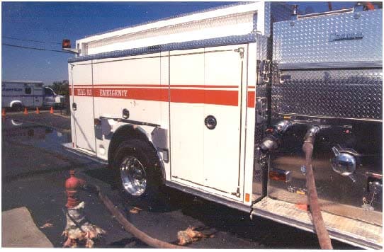
Photo 1. Illustrates the engine’s passenger side discharge panel. It also depicts the fill line connected to the #4 discharge and water holding tank’s hydrant.
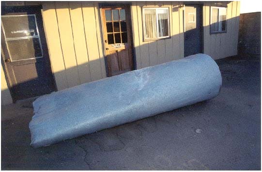
Photo 2. The 525-gallon steel water holding tank involved in this incident.
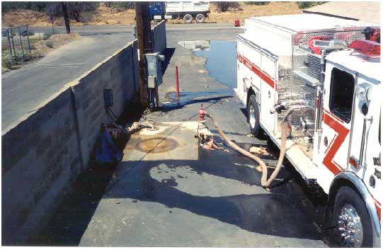
Photo 3. Illustrates the original placement of the water holding tank, the hydrant, and the plumbing system in relation to the passenger side of the engine.
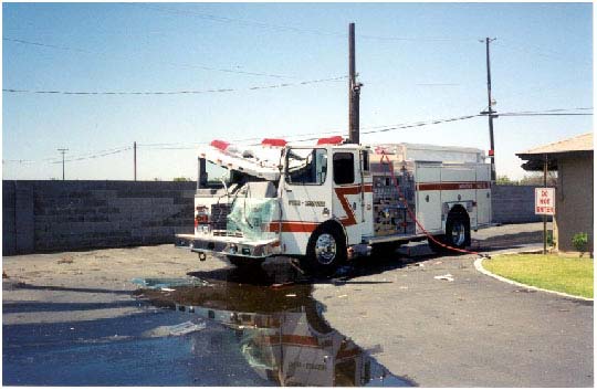
Photo 4. Depicts the point of impact by the holding tank on the cab of the engine.
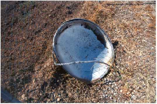
Photo 5. Illustrates that the holding tank failed near the bottom seam.
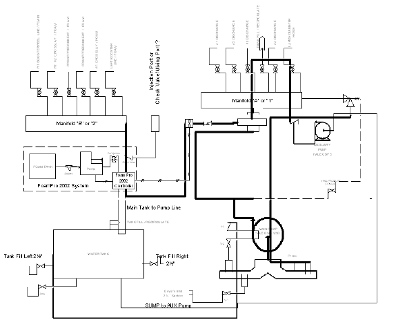
Diagram 1. Plumbing Diagram.
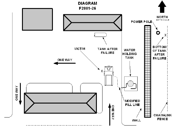
Diagram 2. Location of incident.
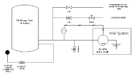
Diagram 3. Tank Diagram.
This page was last updated on 7/30/02
