HIGHWAY WORK ZONE SAFETY
Construction Equipment Visibility
Test Procedure
Physical Measurements
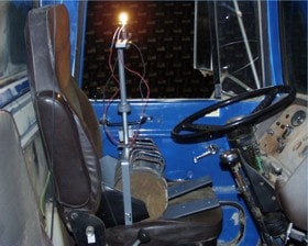
The physical measurements test procedure for developing Blind Area Diagrams was conducted in the semi-anechoic building used for sound testing at Caterpillar’s Peoria Proving Ground. This facility provided the dark environment needed for the light/shadow technique that was used following methodology in the ISO 5006 procedure. With this methodology, light bulbs, or more specifically filaments, are used to simulate the operator’s eyes. The bulbs are mounted on a bar that allows each bulb to be moved horizontally, from a center position, up to 202.5 mm (405 mm total bulb spacing). The actual light support device used for the physical tests is shown in Figure 1. The filament spacing represents the range of eye movement that an operator will use to look around a blockage. Each filament casts a separate shadow due to a visibility blockage. If the two shadows overlap, a dark shadow is created, called a masking or blind area, where neither filament can “see.” If the two shadows do not overlap, there is no blind area because at least one filament can “see” the area of interest.
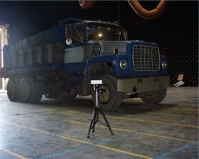
A Pentax R115N Electronic Total Station surveying instrument was used to collect the data points that define the machine boundary and the blind areas. This instrument does not require a prism reflector for measurements and provides rectangular coordinates of the target. The target was mounted on an adjustable height stand for the planes 900 mm and 1500 mm above the ground plane. See Figure 2.
Figure 1. Light support device test setup.
Figure 2. Adjustable target stand.
Physical Measurements Test Procedure
- Initial machine placement: The test engineer places the center of the Seat Index Point (SIP) measuring device directly above the center of the visibility test circle. The best practice is to use a plumb bob to center the filament side-to-side with the front-to-back visually approximate.
- Final machine placement: Once the side-to-side position is accurate, place the filament fixture in the cab at 680 mm above and 20 mm in front of the SIP. Use a plumb bob and straight edge to mark a reference point on the side of the machine. Hold the plumb bob at the reference point and move the machine forward or backward as necessary.
- Position the implement attachments as described in ISO 5006. The position depends on the type and size of the machine being tested.
- Adjust the bulb filament spacing for the sector of vision being recorded according to ISO 5006.
- Position the support bar holding the light bulbs perpendicular to the visibility blockage being measured. A technique called “focusing” is used to ensure that the light bar is perpendicular to the vertical blockage. To “focus,” the light bar is moved +/- 45 degrees from the approximate perpendicular position. The light bar is “focused” when the dark shadow, if there is one, is at its minimum width. If there is no dark shadow, the blockage does not create a blind area for the given filament spacing. Horizontal blockages are created by hoods, fenders, the bottom edges of windows, etc. and do not have a single point perpendicular to the blockage. In this case, the light bar is rotated to positions that will reasonably capture the blind area.
- Measure and record the blind areas on the ground plane using the surveying instrument and target.
- Repeat steps 3 – 6 until all blind areas in all of the sectors have been recorded.
- Measure indirect visibility areas of mirrors.
- Set surveying target height to 900 mm.
- Repeat steps 3 – 8.
- Set surveying target height to 1500 mm.
- Repeat steps 3 – 8.
Disclaimer: The blind area diagrams are reproduced as received from the contractor, Caterpillar Inc., under NIOSH contract number 200-2002-00563. The opinions, findings, and conclusions expressed herein are not necessarily those of the National Institute for Occupational Safety and Health (NIOSH). Furthermore, mention of any company or product does not constitute endorsement by NIOSH.


