Advanced Tutorial on Wireless Communication and Electronic Tracking: Communication System Performance
2.1 General Performance Consideration
The discussion of wireless communications systems begins by considering the general characteristics of the systems and addressing the following questions:
- What is necessary to establish communications between two radios?
- What frequency or frequencies are appropriate for use in a mine?
- What frequency or frequencies must not be used to avoid potential interference?
- How much radio frequency (RF) power is allowable for use in underground coal mines?
- How much bandwidth is needed?
- What is bit error rate (BER) and how is it related to reliability?
- How are communications components interconnected to form a network?
- Why is a network necessary?
- How does a network configuration or topology affect the ability of the network to survive an accident?
- On what basis are different systems or technologies compared?
- What are the appropriate metrics for measuring performance?
Another important consideration is the basic type of wireless communications system, i.e., primary or secondary. Primary communications systems are those used by miners for providing daily underground and surface communications throughout their shift. These systems are typically hand-held devices operating in the conventional radio bands (e.g., very high frequency (VHF), ultrahigh frequency (UHF), 2.4 GHz, 5.8 GHz). Leaky feeder and node-based systems are examples of such primary systems. Secondary communications systems are those which operate in nonconventional frequency bands (100 Hz to 1 MHz) and are not readily portable, but they may be more likely to remain operational following a mine accident or disaster. Medium frequency (MF) and through-the-earth (TTE) systems are examples of secondary systems that may provide survivable alternative paths to primary communication systems. All of these systems will be discussed in more detail in the following sections of this chapter.
2.1.1 Physical Communications Link
The essence of communications between two radios is the establishment of a physical communications link between the devices. Figure 2-1 shows the factors that contribute to the simplest communications link between a transmitter (Tx) and a receiver (Rx). The radio frequency (RF) power flows from the sender (transmitter) to the receiver along this link. For example, the power applied to the Tx antenna travels down the cable connecting the transmitter to the Tx antenna, then to the Tx antenna, through the medium in which the electromagnetic (EM) signal travels, through the Rx antenna, and through any cable that might be used to connect the Rx antenna to the receiver. At this point in the communications link, the power is referred to as the receiver power.

Figure 2-1. Components of a simple wireless communications link.
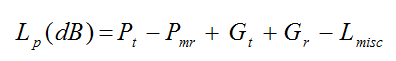
A link budget analysis is the quantitative evaluation of the factors that contribute to RF power gain or loss in establishing a communications link between a transmitter and receiver. The purpose of a link budget analysis is to calculate the allowable path loss (Lp). The allowable path loss is the maximum energy that can be dissipated in the transmission medium before the communications link is no longer possible. Because the path loss increases with distance, the maximum allowable path loss can be used to estimate the maximum possible separation distance between the transmitter and receiver, which is referred to as the transmission or coverage range. The link budget analysis can also be used to compare the performance of different systems and system configurations. The path loss is calculated as follows:
(1)
Equation 1 shows that the allowable path loss (Lp) is dependent on the Tx power (Pt), Rx signal level threshold or minimum received power (Pmr) which accounts for noise, Tx antenna gain (Gt), and Rx antenna gain (Gr). Any additional losses, such as cable losses, are categorized as a miscellaneous term (Lmisc). All terms are in decibel (dB) units; the antenna gains are in Decibel (dBi); and Tx and Rx powers are in dBm or dBW (see Appendix B.1.1). To establish the communications link, the received power has to be above the receiver signal level threshold; otherwise, the signal may be too weak, which means that the receiver cannot process the signal and the link cannot be created.
Most of the terms in Equation 1 that contribute to establishing and maintaining the communications link are fixed by the equipment being used. The values of those terms can be obtained from the manufacturers, except for the Pmr term which includes natural and manmade noise and is a site-specific (mine-specific) consideration. The equation yields the allowable path loss or propagation loss (Lp).
Propagation is the common term used for describing electromagnetic waves (or energy) traveling through a medium. The propagation loss is largely a function of the transmission medium characteristics and the wavelength of the electromagnetic energy, as will be discussed in Section 2.1.4.
At very low frequencies (less than about 10,000 Hz), EM waves can propagate directly through the earth. At somewhat higher frequencies (100-1,000 kHz), EM waves couple to, and are transported by, metallic conductors. At even higher frequencies (greater than about 100 MHz), the waves may propagate significant distances entirely through the air. For each of these media and frequency ranges, the attenuation due to propagation loss is quite different. In addition, as the frequency changes, the performance and size of the antennas change dramatically. The link budget analysis (Equation 1) is used to account for these changes.
A variety of factors determine the effective receiver sensitivity (Pmr) and the effective transmit power (Pt). Essentially, Pmr is the ability of the receiver to "hear" the signal, and Pt is how "loud" the signal is when sent out from the transmitter antenna.
For a physical communications link, the primary information transferred is either voice or text messages, or data messages from a sensor. Text messages can be entered into a computer-like device to generate an electrical version of the message (the data are already in an electrical format), but spoken communications are sound waves (pressure waves in air) that must be converted to an electrical format through the use of a microphone. A microphone contains a speaker or piezoelectric crystal, and oscillations of the speaker diaphragm or crystal convert the pressure waves into electrical signals.
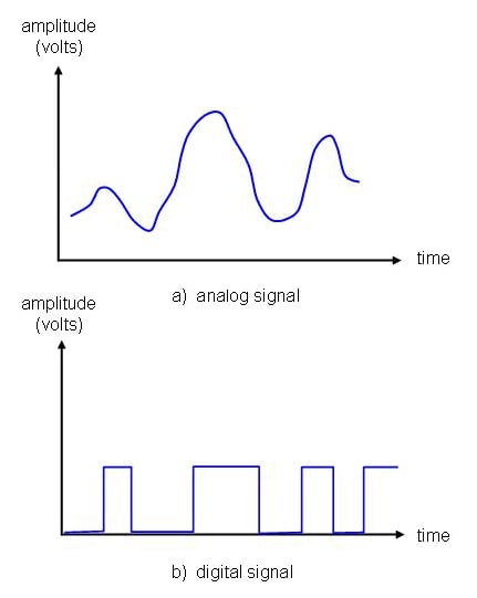
Figure 2-2. Analog and digital signals.
The electrical version of the voice signals from a microphone are analog signals; they are continuous current or voltage signals that vary smoothly with time, as shown in Figure 2-2a. In contrast, a text or data message is likely to be a digital signal. A digital signal is one in which the signal intensity maintains a constant amplitude for some period of time and then abruptly changes to another constant level, as shown in Figure 2-2b.
Current CT systems can operate using either analog or digital format. Analog systems generally have fewer components and are less expensive than digital systems, but digital signals have the advantage of being able to be read, stored, and manipulated by computers. Digital signals can also be copied an unlimited number of times and transmitted long distances without the pattern changing or degrading, as long as the digital information is not lost or corrupted.
Just as a message can be in digital (text message) or analog (voice) format, the transmission of the message can be in either digital or analog format. Figure 2-3a shows a simplified analog transmission model (the message transmits as an analog signal). The source (transmitted) message, which might be voice or data, can be in analog or digital format. A device called a modulator combines the analog or digital signal with the carrier frequency (the assigned or advertised frequency of operation); i.e., the modulator varies the carrier frequency along with the analog or digital signal. The modulated signal travels to the transmitter, where the analog message is sent out over the medium. When an analog signal arrives, the process repeats in reverse order, or demodulates, to recover the analog message.
Figure 2-3b shows a digital transmission system. The Encoder/decoder(codec), also called a codec when applied to analog signals, digitizes the analog signal by sampling it at certain time intervals as shown in Figure 2-4. There are several methods of digitizing analog signals; one is discussed briefly below.
Figure 2-4a illustrates the digitization of an analog signal. Figure 2-4b illustrates the sampling of the voltage amplitude of the signal at discrete time intervals represented by the regularly spaced vertical dashed lines. A discrete value is chosen from the closest to one of 2n allowable values, where n is the number of bits represented in the voltage amplitude at each time interval. As an example, if the voltage amplitude is confined to the interval of -1 to +1 volts and an 8-bit digitizer (n = 8) is chosen, the number of voltage levels is 28 = 256; the voltage resolution is the voltage interval divided by the number of levels, (1-(-1))/256 ~ 7.8 millivolts. Each voltage level would be represented by an 8-bit number containing only 0s and 1s, such as 01101001. A sequence of binary values now represents the analog signal. Using this example, Figure 2-4c shows what a reconstructed signal might look like.
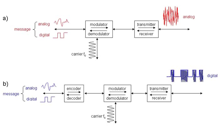
Figure 2-3. Simplified analog and digital communications models.
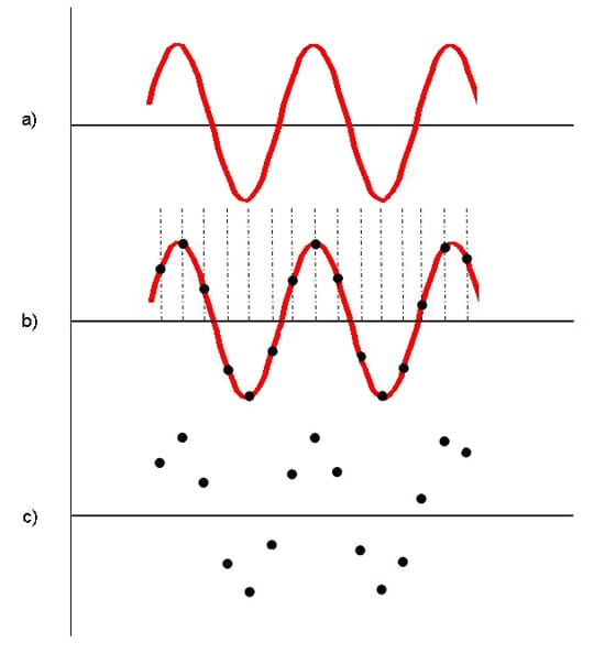
Figure 2-4. Digitization of an analog signal.
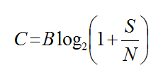
The data rate, number of bits per second (bits/s), that a channel can transmit defines the channel capacity. There is an upper limit to the data rate, given by Shannon’s Channel Capacity Theorem [Stallings 2007]:
(2)
where
C = channel capacity (bits/s),
B = channel bandwidth (Hz),
S = signal strength (watts),
N = noise power (watts).
Equation 2 indicates that if the signal-to-noise ratio signal-to-noise ratio (SNR) (S/N in Equation 2) increases, the channel capacity (C) also increases. If the noise power (N) increases but the signal level remains fixed, S/N decreases as does the channel capacity (C). A larger channel bandwidth (B) will accommodate a higher data rate (C) if the other terms in the equation are unchanged.
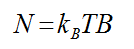
For all communications systems, the received signal is a combination of the transmitted signal, various distortions imposed by the transmission system, and unwanted signals (noise) inserted somewhere between the transmission and reception process. One category of noise is thermal noise. Thermal noise is due to thermal agitation of electrons and is present in all electronic devices. Thermal noise is uniformly distributed across the channel bandwidth and is calculated from the following formula (Equation 3):
(3)
where
N = noise power (watts),
kB = Boltzman’s constant (1.38 X 10⁻²³ J/K),
T = system temperature (Kelvin scale), usually assumed to be 290°K,
B = channel bandwidth Hz).
Consider the thermal noise as the theoretical noise floor for an ideal receiver. A real receiver noise floor will always be higher due to additional noise sources within the device. The noise figure (NF) is a measure of the amount of noise added by the receiver itself. A typical receiver might have a NF ~ 7 to 15 dB.
As an example, a receiver might have a bandwidth B = 80 kHz for a voice channel. Assuming the device has a NF = 7 dB, the receiver noise floor is shown in Equation 4 as follows:
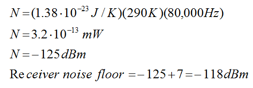
(4)
The receiver signal-level threshold (Pr) is a number usually supplied by the manufacturer, but it may be estimated if the modulation technique and allowable error rates are known. As mentioned earlier, modulation is the method of converting analog or digital information to signals at the desired RF transmission frequency. A number of modulation techniques are available, and the method selected impacts the system bandwidth, power efficiency, sensitivity, and complexity.
Amplitude modulation (AM) and frequency modulation (FM) are common examples of modulation methods used in commercial radio. Other examples of modulation techniques are frequency shift keying (FSK), phase shift keying (PSK), and orthogonal frequency shift keying (OFSK) [Stallings 2007]. For the purposes of this tutorial and link budget analysis, it is necessary to understand that the modulation technique determines the signal level above the noise or the signal-to-noise ratio (SNR) which is necessary for a receiver to achieve a specified level of reliability in reading bits.
The bit error rate (BER) is the probability of incorrectly reading a bit. In binary digital communications systems, an information sequence consisting of binary digits (bits) can represent the data. Each bit has one of two possible values (0 or 1), and each bit is associated with a distinct waveform. Consequently, bits have several properties that derive from their waveform representation:
- The bit duration Tb (sec) is the duration of the waveform associated with each bit.
- The bit rate (or data rate) R (bits/s or Hz) is the number of bits transmitted per second.
- The bit energy Eb (energy required per bit of information, Joule) is the energy contained in the bit waveform.
The bit rate relates to the bit duration by:
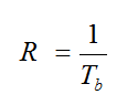
(5)
The bit energy relates to the signal power S (watts) by:
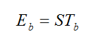
(6)
Assume that the thermal noise power is uniform over the bandwidth, then:
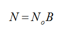
(7)
where
N and B were previously defined and,
No = thermal noise in 1 Hz of bandwidth.
If the value of Eb/No is known, the SNR is:
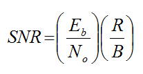
(8)
where
R = data rate,
B = channel bandwidth (Hz).
Equation 8 suggests that if the data rate (R) increases, the SNR must also increase. If a larger bandwidth signal is used, the required SNR decreases.
Figure 2-5 shows BER plots for PSK and OFSK modulation schemes. Acceptable BER values typically range from 10-3 to 10-6 [Freeman 2005]. As an example in applying the equations above, if the acceptable BER is given as 10-6, the required data rate is assumed to be R = 40 kilobits per second (kbps) for digital voice channel communications, and the modulation technique is PSK, then Figure 2-5 gives the corresponding Eb/No value of about 10.4 dB or a numeric value of 11, and the following Equation 9 is derived from Equation 8:
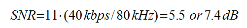
(9)
![Figure 2-5. Probability of bit error rate (BER) for two modulation methods [Freeman 2005].](../../../UserFiles/content/emergencymanagementandresponse/commtracking/commtrackingtutorial2/2-5.png)
Figure 2-5. Probability of bit error rate (BER) for two modulation methods [Freeman 2005].
For this example, the receiver signal must be 7.4 dB above the receiver noise floor to achieve the desired BER, therefore:
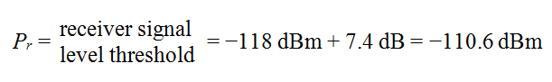
(10)
In interpreting this example, notice that the receiver signal power started at a level limited by thermal noise, -125 dBm. The receiver components raised the noise floor 7 dB to -118 dBm. The signal had to be greater than the noise level by 7.4 dB to achieve the required BER, raising the required receiver threshold level to -110.6 dBm. The receiver power is a large negative number because the receiver is very sensitive; -110.6 dBm is equivalent to 8.7 x 10⁻¹⁵ mW, but the terms that make the receiver level a less negative number (in dBm) mean that the required minimum receiver power is increasing. This increasing power affects the path loss of Equation 1. The maximum path loss depends on the magnitude of Pr; as the magnitude of the minimum Pr increases (as in the example above), the maximum path loss decreases, as does the allowable separation distance between the Tx and Rx. Hence, an increased noise level, or a larger required SNR, will decrease the maximum separation distance between a Tx and Rx.
Although the discussion in this section has focused on the factors that control a physical link between two communicating devices, in general there are multiple links used to connect a source and destination. Figure 2-6 illustrates a more complicated communications path between the sender (transmitter) and receiver, but one that is also more common. The Tx and Rx access a network (inside the dashed line in this figure) to establish communications. The message relays between sequential communications components (nodes) before reaching the receiver. This leads to the discussion of networks in the next section.
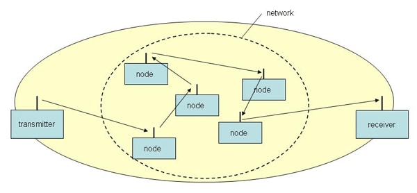
Figure 2-6. Communications via a network.
2.1.2 Networks
A network is the interconnection of multiple communications components designed to extend the area of coverage and the number of users able to access the services provided. Due to the limited range of a single wireless communications link and the large geographical extent of modern underground coal mines, any of the wireless communications or electronic tracking systems installed in a mine will require a network of some sort, except possibly in a very small mine, i.e., < 600 m (2,000 ft) in length.
Topology is the configuration of the network components. The choice of topology plays a major role in the performance of the network and its likelihood to survive accidents (i.e., its survivability). Figure 2-7 shows several basic types of network topologies. The green circles represent nodes, and the lines represent connections between the nodes. The connections may be hard-wired metallic conductors, fiber-optic cables, or wireless links.
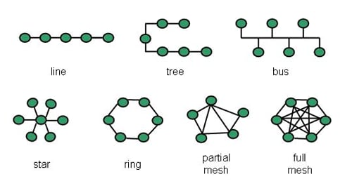
Figure 2-7. Examples of standard network topologies.
There are advantages and disadvantages to each topology pictured. The line topology is simple, and failures are easy to isolate. However, if the leftmost node is on the surface and there is a failure at one of the connections or other nodes, the nodes to the right (inby the working face) of the failure have their communications cut off. Thus, the network is vulnerable to a single-point failure.
The tree topology is an improvement over the line topology simply because a failure on one of the branches does not affect the other branches, but each branch has the same single-point failure-mode potential as the linear structure. In the full-mesh topology, each node connects to every other node. Thus, a miner accesses one of the nodes with his radio link, but the signal could take multiple paths to reach the intended receiver. In addition, if one node fails, there are multiple paths around the failed node. However, it is unlikely that the full-mesh topology would ever be implemented in an underground room-and-pillar coal mine. With the many thousands of feet of mine entries to cover, it would be impractical or impossible to interconnect each node to every other node. A partial mesh offers many of the advantages of the full mesh and is much more practical in the mine environment.
2.1.3 Management of the Electromagnetic Spectrum
The MINER Act of 2006 requires mine operators to install wireless, or partially wireless (see MSHA Program Policy Letter No. P11-V13, April 28, 2011), communications and tracking systems into a mine environment that previously has had a very limited number of intentional RF emitters (transmitters, wireless remote controls, etc.). Consequently, there is the potential for electromagnetic interference (EMI). EMI occurs in a system when undesired electromagnetic (EM) energy from another RF system interferes with the reception or processing of a desired signal. In contrast, electromagnetic compatibility (EMC) is a desirable condition in which electronic systems are performing their desired functions without causing unacceptable performance degradation to other systems or being the victim of RF radiation which causes unacceptable degradation in the system itself. EMC is established when any potential EMI between systems has been eliminated or reduced to an acceptable level. EMC has two aspects: (a) a system should not generate EM disturbances that causes a malfunction in another system (usually referred to as the emission aspect) and (b) a system should be able to operate in its EM environment without risk of malfunction (usually referred to as the immunity or susceptibility aspect).
In trying to reduce EMI, it is essential to identify the devices emitting RF energy and to determine the frequencies at which these devices work. Spectrum management is the term that indicates the management of the use of radio frequencies. Table 2-1 lists possible radio frequency emitters in a coal mine.
| Frequency | Application | Comments |
|---|---|---|
| 300-10,000 Hz | Personal emergency devices | Through-the-earth communications |
| 70-500 kHz | Proximity detection devices | Audible and visual warning |
| 300-800 kHz | Medium frequency radios | Voice, text |
| 150-175 MHz | VHF leaky feeder systems | Voice and low bandwidth data |
| 400-410 MHz | Miner or asset tracking systems | Radio frequency identification (RFID) |
| 450-470 MHz | UHF leaky feeder systems | Voice and low bandwidth data |
| 490 MHz | Remote-operated continuous miner | Remote control of continuous miner |
| 900 MHz | Active radio frequency identification (RFID) tags | RFID to track miner’s location |
| 900 MHz | Line-of-sight radios | Voice, text |
| 900 MHz | Rescue robots | Robot control |
| 2.4 GHz | Rescue robots | Video |
| 2.4 GHz | Line-of-sight radios | Voice, text |
Another source of interference is noise, which consists of random electrical voltages. EM noise can originate within a radio receiver as discussed previously, or it can be external in origin. External noise can be classified as either manmade noise or as natural noise. In a coal mine, manmade EM noise can be generated by electrical equipment (e.g., motors), electronic equipment (remote-control devices), transformers, power lines, and electrical/mechanical switching devices. Electrically powered machinery used in mining also produces strong, low-frequency noise when starting up or when the power demand switches from high to low (or vice versa).
Lightning is one source of naturally occurring noise. This EM noise is low frequency, and the propagation loss is so low that its possible noise contributions could come from anywhere in the entire world. Wires that run into the mine can carry lightning and other EM noise generated from outside the mine.
2.1.4 Modeling and Analysis
The link budget analysis, introduced earlier, is a powerful tool for estimating the maximum coverage area for a CT system. It can also help determine the spacing between any pair of antennas to ensure reliable and high-quality communications.
Aboveground, hand-held radios can achieve communications between users separated by several miles. However, those same radios may only reach a few hundred feet in an underground mine. This dramatic change in performance is due to the impact of the mine environment on the propagation of EM waves.
The EM waves radiated by the Tx antenna travel through the surrounding medium, losing energy as they travel. This process is called EM wave propagation, and results in a propagation loss (path loss). As an example, consider the EM propagation of ultrahigh frequency (UHF) waves in a mine entry. It is possible to describe the path loss by modeling the tunnel as a waveguide [Emslie et al. 1975]. EM waves can propagate only if the wavelength is less than twice the tunnel dimensions, and then only certain prescribed modes of propagation are allowed. The modes dictate allowable angles of reflection of the wave as it propagates down the tunnel. The fundamental (lowest order) mode appears to adequately describe the path loss some distance (typically a few hundred feet) from the transmitter after including an insertion loss (Linsertion) to account for the poor coupling of the Tx and Rx antennas to the fundamental waveguide mode. The RF fundamental mode signal attenuation (Cmode) after the first few hundred feet from the Tx antenna varies linearly with the distance z down the entry. Hence, as the distance from the transmitter increases, the path loss increases.
The model [Emslie et al. 1975] also mentions several other effects that impact the path loss. One effect is due to the wall roughness, which permits some of the RF energy to be diffusely scattered by the interaction of the EM wave with the walls. Because the wall scattering (Cwall) is assumed to occur continuously as the EM wave propagates down the tunnel, it also varies linearly with z. Another effect is due to the possibility of the wall spacing (or floor and ceiling spacing) becoming gradually smaller or larger as measured by an angle Θ (tilt angle). The attenuation due to tilt (Ctilt) is also a linear function of z. Additional losses can be modeled for UHF signals propagating down a turn, such as a crosscut, but these losses will not be discussed further here. Equation 11 gives the line-of-sight (LOS) path loss for UHF propagation down an entry for the effects previously discussed. Each of the constants (C) may depend on the wavelength of the UHF wave, the height and width of the entry, and the electrical properties (relative dielectric constants) of the walls, floor, and roof.
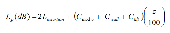
(11)
Representative values of the terms on the right side of the equation are (assuming a 14-ft-wide by 7-ft-high entry, frequency of 900 MHz, wall roughness of 4 in, and tilt angle of 1 degree):
Linsertion = 22 dB; Cmode = 1.4 dB/100 ft; Cwall = 0.2 dB/100 ft; Ctilt = 1.2 dB/100 ft.
Hence, the path loss at 1,000 ft is 72 dB. Equation 11 indicates that as the distance z increases, the path loss increases as expected. The dependence of Lp on mine-specific features illuminates the difficulty in applying generic CT performance statements to all mines.
As seen above, the propagation loss may depend on the surrounding medium (wall, roof, floor roughness), any blockages along the path (e.g., mining equipment), frequency of the propagating wave, and dimensions of the mine entry. Determining the path loss may require the development of a model of the behavior that would include a detailed computer analysis. The more likely scenario is the development of "rules of thumb" for performance in a particular mine based on device testing in different parts of the mine. These "rules of thumb" would then become the basis for designing the CT system and expansion planning, followed by system testing after installation.
In addition to link budget analysis, an EMI analysis may be used to determine the level of undesired power received by a receiving system (a possible victim of EMI) due to radiation from a transmitting system (a possible source of EMI). In order to avoid interference, an EMI analysis may also be necessary to determine the required spacing between antennas or an alteration of the frequency used by the source and victim (receiver).
2.1.5 Maintenance and Testing
Coal mine communications and tracking systems require periodic maintenance for optimum performance. Although these are rugged systems, the mine environment is very harsh. The RF system manufacturers should specify periodic maintenance checks. For example, when the power shuts down during emergencies, most systems will have battery backups. These batteries need to be checked periodically to ensure they are operational. Even rechargeable batteries in hand-held devices have a terminable lifetime associated with them, requiring periodic replacement.
To verify that the coverage is fully functional, periodic testing of CT systems is a necessary routine in the mine. Testing can be quantitative or qualitative. Quantitative testing requires specialized equipment to measure radio signal strength as a function of location throughout an area. Qualitative testing will likely involve spot checks of communications links using a series of "Can you hear me now?" interchanges between underground and surface users.
2.1.6 Performance Metrics and Goals
Performance metrics and performance goals for CT systems in underground coal mines is a controversial topic. When it comes to specific metrics, there are diverse opinions as to what those metrics should be in relation to the achievable performance goals. This section reviews the diversity of opinions and the difficulties in establishing these metrics and goals. This background will be followed by a discussion of sample metrics for underground coal mines.
For the purpose of this tutorial, performance metrics are measures of performance based on system behavior over a given period. These measures can be either qualitative or quantitative. Qualitative measures require some level of human judgment, e.g. ease of installation and difficulty in troubleshooting. Quantitative metrics are directly measured or involve numbers that can be explicitly assigned—for example, bit error rates (BERs), received signal strength indications (RSSI), and system update intervals.
A performance goal, as used here, is the minimum or maximum value achievable for a given performance metric. Generally, it is relatively easy to obtain agreement on qualitative performance goals. Most people would agree that CT systems should be:
- Able to provide two-way communications.
- Able to determine a miner’s location.
- Easy to use.
- Easy to install and maintain.
- Safely operable in both pre- and post-accident scenarios.
- Reliable in both normal and emergency situations.
- Survivable in being able to remain operational post-accident.
Quantitative performance metrics and goals, however, cause opinions to rapidly diverge. For example, the following questions arise for a CT system:
- What mechanical and explosive forces and extent of damage must the system survive?
- How often should the system be tested, and how is it verified to be properly functioning?
- How long does a system have to remain operational post-accident?
- What percentage reliability or availability is required of a system?
- What is the maximum acceptable time for routine maintenance and repairs?
- What is the maximum acceptable delay for a miner’s message to reach the surface (during normal operations and/or post-accident)?
- What constitutes sufficiently safe operation of battery-powered devices in a potentially explosive (methane and/or coal dust) environment?
- How accurately does a miner’s location need to be determined?
- How is a system tested once survivability goals are established?
There are several reasons why it is very difficult to answer these questions and to establish quantitative performance metrics that will have consensus agreement. These reasons include:
CT systems operate differently underground. The propagation characteristics of electromagnetic energy are different underground as compared with "free space" or aboveground environments. Therefore, the common methods used for validating these metrics do not apply. For example:
- Underground coverage is a linear parameter measured in feet or miles. Aboveground coverage is an area measured in square miles or square feet.
- Working places are constantly advancing and retreating in underground coal mines, whereas aboveground metrics are largely based on fixed infrastructure.
Consequently, aboveground methods for calculating survivability and reliability are not well suited to underground applications.
- The underlying system requirements are different. The primary purpose for installing CT systems in underground coal mines is to provide post-accident communications that comply with the MINER Act of 2006. Aboveground, most systems exist for productivity enhancements and automation; therefore, survivability and reliability are generally secondary rather than primary performance metrics.
- Survivability and reliability risks and options require installation-specific considerations. A traditional one-size-fits-all solution is not applicable in underground mines. For CT systems, survivability has as much to do with the system layout and installation as it does with the technology selection. Thus, uniformly accepted performance metrics are difficult to achieve within the mining community.
- There are numerous tradeoffs in establishing performance goals. In the design of CT systems, there are instances where methods to achieve one performance goal make it more difficult to achieve another. As an example, steps taken to make a system user-friendly, such as automating certain functions, could lead to a more complex design, increased cost, and perhaps reduced reliability. As another example, extending the time that a system remains operational in an emergency could lead to larger and/or additional backup power-supply locations, thus creating more potential safety problems associated with the batteries. As a third example, coverage goals could drive requirements to install active components in return airways, thus creating safety concerns (potential ignition sources).
- CT systems represent a new technology area for underground mines. Telecommunications companies that are responsible for the reliable operations of these systems operate most communications systems aboveground. In addition, aboveground companies have ready access to service companies that can design and implement systems in those cases where companies elect to have their own infrastructure. This is not the case for the CT systems proposed for use underground. As a result, three issues arise:
- Suitable tools to measure and predict performance in an underground mine environment are limited.
- Personnel expertise, experience, and historical data to formulate performance metrics in the underground mine environment are limited.
- At this time there is very little information relevant to CT systems in any underground mine disaster scenarios that are usable for determining system requirements.
In response to the above issues, new metrics and methods, and possibly even new terminology, will evolve as mine operators and regulators begin to gain experience with these systems. Nonetheless, the mining industry should strive to keep these performance metrics and terminology consistent with other industries as much as is practical.
NIOSH has a variety of efforts underway that will help formulate a basis for deciding what system metrics and goals are appropriate for the underground environment. An internal NIOSH working group has proposed performance metrics that fall into four broad categories:
- Functionality. System requirements from the perspective of the miner and other end users.
- Installation and maintainability. Metrics associated with the installation, maintenance, troubleshooting, and expansion of the CT system.
- Communications and tracking coverage and range. Metrics that describe the service area of the CT system.
- Survivability and post-accident safety. Metrics that describe the ability of a system to continue to safely operate post-accident.
Other metrics and goals are possibly related to system productivity, such as system capacity, cost per foot or mile, mean time to repair, etc. These are not included in the working group examples.
As CT technologies develop, performance enhancements are expected. The following metrics and goals in Table 2-2 are examples to promote discussion within the mining community. These long-term goals represent a view of an ideal CT world in the mine environment; it is likely that some of the long-term goals may not be realistically achievable. NIOSH continues to advocate the development of performance metrics and goals in collaboration with labor, industry, and regulatory agencies. Readers should refer to the latest MSHA and state regulations and policies to understand the minimum performance requirements expected by those agencies.
| General Category | System | Performance Metric | Long-Term Goal |
|---|---|---|---|
| Coverage and range | Comm. | Wireless coverage | Everywhere miners go |
| Coverage range | Tracking | Tracking system reporting area | Everywhere miners go |
| Functionality | Comm. | Wireless communications capability | Voice and data with free-form texting |
| Functionality | Comm. | Peer-to-peer communications | All mobile radios should be capable of radio-to-radio communications without infrastructure |
| Functionality | Comm. | Paging capability | Page all |
| Functionality | Tracking | Tracking data storage requirements | To be developed* |
| Functionality | Tracking | Rescue team victim locator | Audible alarm activated by proximity or radio |
| Functionality | Both | Remote shutdown/power management | System can be turned off and on remotely for power conservation and safety |
| Functionality | Both | Mine operations center (MOC) surface requirements | Real-time graphical display of miners, batteries, and faults/alarms |
| Functionality | Both | Interoperability | Voice and data communications to all devices and locations |
| Functionality | Both | Battery maintenance and monitoring | Reliable monitoring of battery conditions with alarms |
| Installation and maintainability | Comm. | Coverage verification | Monthly verification through "drive" tests |
| Functionality | Tracking | Tracking system update interval | To be developed* |
| Functionality | Tracking | Tracking system resolution | To be developed* |
| Functionality | Tracking | Miner location update interval | To be developed* |
| Installation and maintainability | Both | Maintenance and monitoring | Real-time monitoring of all elements with alarms, end-to-end automated test |
| Survivability | Comm. | Wireless coverage survivability (refers to access link) | Invulnerable infrastructure |
| Survivability | Comm. | Maximum outage area with a single element failure (worst case) | Invulnerable infrastructure |
| Survivability | Comm. | Communications path survivability (pertains to voice/data and tracking system backhaul) | Invulnerable infrastructure |
| Survivability | Comm. | Battery life - communications mobile | MSHA Program Policy Letters (PPL) |
| Survivability | Comm. | Battery life - communications fixed infrastructure | 96 hrs - indefinite with power management |
| Survivability | Tracking | Tracking system survivability | Invulnerable infrastructure |
| Survivability | Tracking | Battery life - tracking mobile | To be developed* |
| Survivability | Tracking | Battery life - tracking fixed infrastructure | 96 hrs - indefinite with power management |
| Survivability | Both | Battery life | Unlimited |
| Post-accident safety | Both | Battery system safety | Invulnerable infrastructure |
| Post-accident safety | Both | Permissibility or safe air validation post-disaster | Invulnerable infrastructure |
*Note: "To be developed" indicates that the development of long-term goals is expected through consideration of ongoing research efforts. These efforts include detailed analysis of the history, types, and duration of disasters in coal mines.
2.1.7 Wireless Systems Considerations
In wireless systems, the antenna performs a critical role in coupling the energy to and from the transmission medium. For an antenna to be effective, the antenna has to be a significant portion of the wavelength. This leads to the problem of the antenna becoming quite large for lower frequencies. Another issue with systems that operate at low frequencies is that they have very little throughput to support general operations where multiple users and significant data traffic are typical.
2.1.8 Point-to-Point Communications
Throughout this tutorial, there is a distinction between a direct communications link between a sender and receiver (one link) and a communications path that requires a network (multiple links) to complete the connection. With point-to-point (P2P) communications there is a direct link between two devices. One example is an intercom system in which a sender presses a button on an electronic device to talk to a recipient who hears the message on a second electronic device. A wired connection links the two devices. Another example is a pair of walkie-talkies (i.e., hand-held radios). They operate similarly to the intercom system, but the connection between the sender and receiver is wireless. Through-the-earth (TTE) communications is another example of P2P communications. An antenna on the surface communicates directly to an antenna in the mine, with only the earth strata as a transmission medium. TTE communications provides an alternate communications link out of the mine at one specific location, but will not provide radio coverage underground at locations far from the area directly below the surface antenna. P2P provides limited communications between two devices, but to extend the communications range requires additional components in the path (i.e., some type of network or a large distributed antenna system such as a leaky feeder).
2.1.9 Wired Communications
Most mines use some type of wired communications system, where "wired" communications means the miner has to use a device that is in a stationary or fixed location. Many of these wired systems communicate data rather than voice. Examples of wired data communications are conveyor monitoring and control, ethernet networks, and pager phones.
2.1.9.1 Twisted Pair
A twisted pair consists of two insulated copper wires twisted around each other. Sometimes the installation uses multiple wire pairs grouped into a single cable. For example, home telephones are connected using a twisted pair. A twisted pair is the least expensive hardwire connection medium.
Standard pager telephones in coal mines use twisted pair to communicate between the surface and miners underground. Several phones are connected in parallel to provide additional communications within the mine, yielding a "party line." Pushing a handset switch on the phone activates the amplifiers in all the phones so that the message broadcasts to anyone within hearing range of a phone.
2.1.9.2 Ethernet Cable
Ethernet cable is generally an eight-wire cable terminating on a RJ-45 connector as used for local area networks (LANs) and at the output of cable and digital subscriber line (DSL) modems for Internet service. These kinds of Ethernet cable are referred to as CAT5E (for LANs) and CAT6 (for Internet) cable; computers are frequently interconnected using this type of cable. Mine sensor data and/or control data may use Ethernet cable as the medium for transferring information, but the distance supported is limited. As a result, several mediation devices allow Ethernet and other signal support in place of coaxial cable or fiber-optic cable. Coaxial cable has lower signal losses and generally better shielding than CAT5E/CAT6 or twisted pair connections, and therefore is less susceptible to electromagnetic interference (EMI). However, coaxial cable is also more expensive than twisted pair.
2.1.9.3 Fiber-Optic Cable
Fiber-optic cables can transfer data at much higher data rates compared to metallic cables. Fiber-optic cable is composed of continuous optical fibers bundled into a flexible cable. This type of cable can replace copper communications cables. Fiber-optic cable uses light pulses to transmit information down fiber lines instead of using electronic pulses to transmit information down copper lines. The cable is much less susceptible to EMI because it uses light pulses rather than electrical pulses. In addition, there is less attenuation than in copper, so the cable can transmit data over very large distances.
The fiber-optic cable requires a translator. The translator accepts coded electronic pulse information coming from copper wire. It then processes and translates that information into equivalently coded light pulses. The process reverses at the other end of the cable, where the translator converts light pulses back to electronic pulses.
Fiber-optic cables are generally more expensive than copper cables. If a fiber-optic cable breaks, it requires more than a simple splice to reconnect it. Fortunately, manufacturers are continually improving the fiber-optic cable designs, making them more robust and more cost-competitive.
2.1.10 Primary and Secondary Communications
Primary communications systems are those used by miners throughout their shifts that provide normal daily underground and surface communications. These systems operate in the conventional radio bands (e.g., VHF, UHF, 2.4 GHz, 5.8 GHz). They use small antennas that allow miners to have wearable devices with long battery life (lasting longer than one shift), and have sufficient throughput for general mining operations. Leaky feeder and node-based systems are examples of primary communications systems.
Secondary communications systems are those which operate in nonconventional frequency bands (100 Hz to 1 MHz). At such low frequencies they require large antennas which are not readily portable or are installed at fixed locations. Also, because of the low frequencies, they do not have sufficient throughput for communicating during general mining operations. Secondary systems have very few active components and appear to have a high potential for surviving a disaster. Medium frequency (MF) and through-the-earth (TTE) systems are examples of secondary systems that may provide survivable alternative paths to primary systems. It should be noted that primary communications systems are potentially vulnerable to a mine emergency or disaster (methane and/or coal dust explosion, roof or rib fall, water inundation, etc.). Survivability of primary systems to these events can be questionable, depending upon the severity and location of the incident.
One approach is to provide an alternate communications path which is truly diverse and highly reliable. It would not have any shared components between the primary and alternate paths that would fail from a common event. A borehole directly to the miner would be the ideal alternate communications path, but a moving borehole is not very practical. Secondary systems with their limited infrastructure needs offer a great potential for an alternate communications path, particularly near the face.
One other possible option is to consider a hybrid system that assumes interoperability between the primary and secondary systems—that is, design the systems in such a way that a low bandwidth secondary communications system would be used as a backup system for the primary communications system. A key goal would be to ensure that miners would still be able to communicate using the same wearable device as used for day-to-day operations.
2.2 Primary Communications: Leaky Feeder Systems
2.2.1 Description
A leaky feeder communications system uses underground hand-held radios that communicate with a radio transceiver (base station), which is usually located on the surface at the mine operations center (MOC), and other hand-held radios carried by the miners underground. Specially designed leaky feeder cable greatly extends the effective range of the base station. The link from the hand-held radio to the cable is wireless. Figure 2-8 shows one type of leaky feeder cable. The cable acts as a distributed antenna, able to receive and transmit radio signals along its entire length. The holes in the outer conductor allow EM waves to penetrate into, or leak out of, the coaxial cable. The cable also acts as a low-loss transmission medium, transporting RF signals over distances many times larger than would be possible without the cable present.
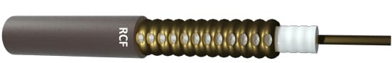
Figure 2-8. Cutaway view of a leaky feeder cable.
Leaky feeder systems typically operate in either the VHF band at around 150 MHz or the UHF band at around 450 MHz.
VHF leaky feeder systems are very common in mines; however, UHF leaky feeder systems are becoming more prevalent. VHF frequencies typically tend to experience lower line attenuation and coupling losses than UHF systems. UHF leaky feeders have requirements that are more stringent for installation and operation than VHF, and are also more costly. However, because of their higher frequency, UHF systems can accommodate larger bandwidths and, therefore, handle more data at higher speeds. In addition, UHF signals from the hand-held radios propagate more efficiently than VHF signals around corners and into crosscuts in the mine. Thus, UHF systems allow the miner to maintain communications when further away from the leaky feeder cable than do VHF systems.
Figure 2-9 shows a cutaway view of a mine with a leaky feeder system installed. Miner 1 and Miner 2 are able to communicate with each other if they are within RF range of the leaky feeder cable.
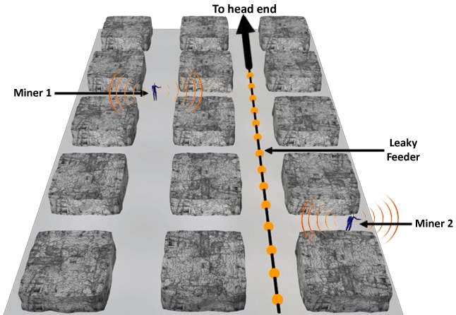
Figure 2-9. Leaky feeder communications system.
2.2.2 Components
A leaky feeder system consists of a number of different components: head end, base station, power coupler, leaky feeder cable, line amplifiers, barriers, splitters, mobile radios, auxiliary antennas, and terminators.
A base station is the main hub of a leaky feeder system. The base station handles communications originating from the MOC and traveling into the mine, and relays information between different branches of the leaky feeder system. A typical base station setup may include a head end, radio repeaters, power supplies, phone interconnect, data servers, and Ethernet for communications systems configured for high-speed data (see Figure 2-10). Components are usually organized and stored in rack mounts. Communications into the mine feed into the head end, which then transmits signals "down" the feeder (see Figure 2-11 in Section 2.2.3) and are referred to as downlink or downstream transmissions. Radio communications originating within the mine travel along the feeder cable "up" to the base station, and are referred to as uplink or upstream transmissions. The uplink and downlink frequencies are not the same because the head end performs a frequency shift before retransmitting the message. Hence, the hand-held radio transmits at one frequency and receives at another. As an example, a VHF radio might transmit at 170 MHz and receive at 150 MHz. Likewise, a UHF radio might transmit at 470 MHz and receive at 450 MHz.
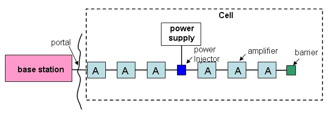
Figure 2-10. Main components of a leaky feeder system.
Note that communications signals between the MOC and the mine portal use a nonradiating cable so that the signals do not radiate from the cable on the surface. However, once underground, this nonradiating cable splices into the leaky feeder cable. DC power is injected into the cable at the head end to power the first few aboveground components located along the leaky feeder.
RF signals on a leaky feeder cable experience a loss in power as the signals propagate down the cable. This is because much of the signal intentionally leaks from the cable along its length. Significant power loss also occurs at junction points where the signal power may split among two or more feeder branches. To combat this loss, line amplifiers, inserted at intervals along the run of the cable, boost the signal strength. In most industry applications, these amplifiers are unidirectional, meaning signals can travel in one direction only. A modification that some manufacturers have made for the coal industry is to provide an option for bi-directional (two-way) amplifiers, meaning that amplification can occur on signals traveling in either direction. Bidirectional amplifiers become particularly important when considering the survivability of the system. Section 2.2.5 discusses this issue in more detail.
The leaky feeder cable itself, using DC power injected at the head end, powers line amplifiers that are close to the MOC. Underground power supplies handle amplifiers further down in the mine. A typical setup will have line amplifiers spaced approximately 450-550 meters (1,500-1,800 feet) apart along straight segments, depending on the frequency and any insertion losses caused by hardware on the line. Figure 2-10 illustrates an example of the periodic placement of line amplifiers in a leaky feeder cable.
Many amplifiers use automatic gain control (AGC). AGC ensures that the power level of the output signal of an amplifier remains constant and independent of the level of the input signal power. This helps to balance the overall power levels along the system and to smooth out any surges or irregularities.
Barriers are devices used to separate power cells or cells, which are the building blocks of a leaky feeder system. These barriers pass RF signals between sections while also isolating the DC power between them. This ensures favorable power characteristics across the leaky feeder system by confining any electrical power imbalances to a single cell. Dividing the leaky feeder system into power "cells" is a necessary modification made for the mining industry to allow the systems to operate in a possibly explosive atmosphere (e.g., methane, coal dust). The requirement is related to the stored energy in the leaky feeder cable, and operators need to ensure that the length of the leaky feeder cable and the size of the "cells" do not exceed what was approved by both the manufacturer and MSHA for the system.
Junctions are points where the leaky feeder cable branches off into separate directions. At junctions, the leaky feeder cable divides into two or more cables by the use of splitters. Splitters maintain proper impedance matching between branches. They can also determine how the signal power divides among each branch in the event that one branch requires more or less power, which is important when designing an efficient communications system.
Mobile hand-held radios are the most common devices used to link to the leaky feeder cable. Other devices eliminate the need to communicate wirelessly through direct wiring into the cable. For example, a radio frequency identification (RFID) tag reader hardwired to a leaky feeder cable relays information back through the cable to the base station in the MOC every time it scans an RFID tag.
It is possible to extend the range of a leaky feeder cable by using an auxiliary or coverage antenna. These antennas usually attach to a branch of the cable to provide coverage in a crosscut or portion of a parallel entry that does not have leaky feeder cable. Auxiliary antennas come in a variety of shapes and sizes and can address a number of radio coverage requirements. Termination antennas on the end of the feeder cable (sometimes called stope antennas) also extend the range of the cable beyond the cable length.
Lengths of lower-quality leaky feeder cable can extend coverage into areas off the main feeder cable. It can be advantageous if this is done in areas where a cable is more likely to be damaged, thereby avoiding harm to a higher-quality (and more expensive) cable. Because a leaky feeder cable can be installed practically anywhere, this is a good solution for areas where obstructions may prevent adequate coverage by an auxiliary antenna.
As the name implies, a terminator unit is at the end of a leaky feeder cable. A terminator unit is a component attached to the end of the leaky feeder cable and minimizes reflections or undesirable effects due to abrupt changes in cable impedance at its ends.
2.2.3 Transmission Media
Figure 2-11 illustrates the communications between two miners talking over their hand-held radios, incorporating two intermediate physical links, each with two parts. The first link, typically called the uplink, is from the sender’s radio to the head end in the base station, consisting of the circled parts 1 and 2 in the diagram (Figure 2-11). The circled part 1 is through the air from the sender’s radio to the leaky feeder cable. Part 2 of the link is along the cable to the base station. The second communications link, called the downlink, is from the base station to the receiver radio, and it also consists of two parts. The first part of the link, indicated as part 3 in the diagram, follows a different branch (although, depending on the receiver location, it could be the same branch) of cable to where the radiated signal travels through air to the receiver (part 4).
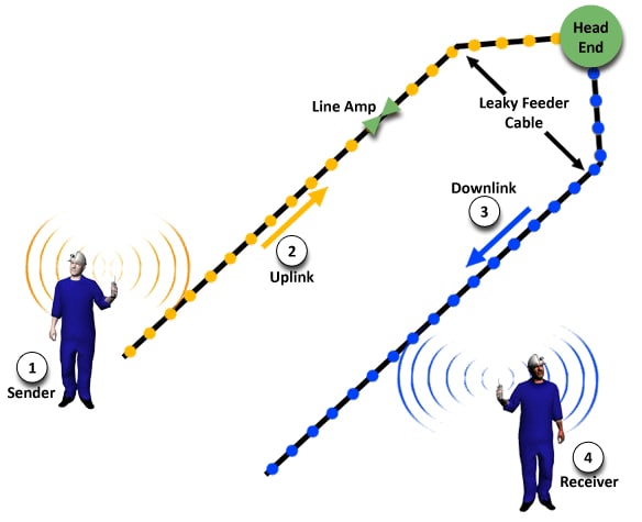
Figure 2-11. Communications link between sender and receiver.
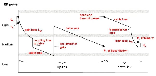
Figure 2-12. Conceptual link budget analysis for leaky feeder system.
Each of the four parts can have individual link budget analysis which, when combined, determine if the entire physical link is feasible. Figure 2-12 is a graphical illustration of the link budget analysis. Starting the uplink analysis at the left side of the graph is the sender’s radio transmit power (Pt) and an immediate jump to account for the radio’s transmit antenna gain (Gt) which is assumed to be positive. The next link is the free-space path loss of the RF signal traveling through the air. Next, there is a coupling loss as the leaky feeder cable intercepts part of the RF signal. As the signal travels down the cable, there is a cable loss.
When the signal reaches the line amplifier, the signal level is increased by the gain of the line amplifier. Further line losses occur until the signal reaches the base station. The base station amplifies the signal and retransmits it (at a different frequency) to begin the downlink portion of the link budget analysis. There are losses in the cable until the signal reaches the location where it is nearest to the receiver radio. In converting from a signal in the cable to a signal in the air, there is a transmission (or coupling) loss. As mentioned before, there is further loss as the RF signal travels through the air. However, there can be an increase in RF power assuming that the receiving antenna has positive gain. The final number is the received power (Pr) in the receiver’s radio. The Pr has to be above the receiver signal-level threshold of this radio for the link to be viable.
The manufacturer can supply most of the values used in a link budget analysis. The sender and/or the receiver can affect the free-space path loss through the air by their actions. For example, if the sender or receiver moves further from the leaky feeder cable, the path loss through the air will increase, resulting in a decrease in Pr. At some distance from the leaky feeder cable, the physical link ceases to be viable.
2.2.4 Network Operations
Figure 2-10 introduced the power cell as the building block of a leaky feeder system. Cells combine through the barrier component, which brings the ends of two leaky feeder cables from adjacent cells close together so that RF signals can jump the gap between them. The gap provides direct current isolation between the cells so that powering the line amplifiers in one cell is independent of another cell. The network thus assembled is linear, with the head end at one end. This topology is especially compatible with the long entries of many mines. Figure 2-13 shows the linear topology schematically.
It may be desirable to have communications in parallel entries, in which case a tree topology (Figure 2-14) is used. Because all communications must travel through the head end, it acts as the base of the tree.
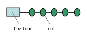
Figure 2-13. A leaky feeder system using a linear topology.
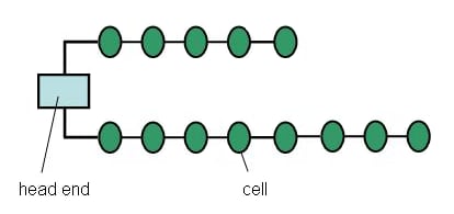
Figure 2-14. A leaky feeder system using a tree topology.
More elaborate topologies can be used to enhance the survivability of the leaky feeder system or to increase the area of coverage. The next section discusses some of these options.
2.2.5 System Implementation
The inherent linear nature of the leaky feeder system makes it especially suited for providing radio coverage in long entries. Figure 2-15 demonstrates one method in which radio coverage is extended down parallel entries.
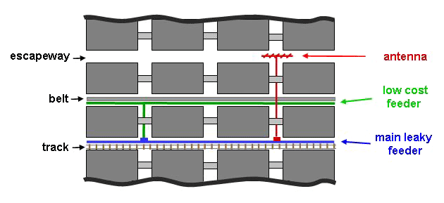
Figure 2-15. Ways to expand radio coverage of a leaky feeder system.
Figure 2-15 illustrates additional ways to extend the main leaky feeder radio coverage. One method is to splice a lower-cost, lower-performance cable into the main feeder cable rather than running a new cable all the way to the head end. An antenna spliced into the main cable can also be used to extend radio coverage to strategic areas.
However, it should be noted that the linear nature of the leaky feeder makes it vulnerable to certain failures. For example, if a roof fall either damages or breaks the cable, all communications inby the break will cease.
Building in redundancy increases the survivability of communications. If an independent, redundant leaky feeder cable exists in a parallel entry, it may remain operational in the case of a localized roof fall that breaks the main cable. In this case, any miners cut off from the main communications could move to another entry to re-establish communications with the surface.
Providing an alternate communications path (ACP) carries the idea of a redundant path to enhance communications survivability one step further. An ACP reaches the surface at a point separated by a significant distance from the normal communications exit point. Figure 2-16 shows an example where the main leaky feeder exits the mine at an elevator shaft. An accident such as a methane or coal dust explosion breaks the main communications link. An ACP provides a leaky feeder exit to the surface through an airshaft or borehole. A surface connection re-establishes communications between the miners inby the accident and the MOC where the primary base station is located.
An RF message on the main leaky feeder cable inby the accident may need to change its direction of travel on the cable. For example, as shown in Figure 2-16, if the sender is inby the accident but outby the ACP to the surface, the sender’s message would have to change its propagation direction. Special bidirectional leaky feeder amplifiers in the cable will permit this reversal of direction.
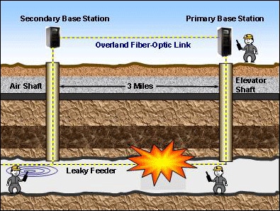
Figure 2-16. Example of an alternate communications path (ACP).
There are additional protective measures that can be taken to increase survivability, or harden the system. For example, there are measures to harden the leaky feeder cable against roof falls, such as encasing the cable in pipe or conduit made of a nonconducting material like PVC, which permits the penetration of RF signals. Burying the encasement at a shallow depth or coating it in protective material such as shotcrete can also help to protect the cable.
For safety reasons, the mine may shut off electrical power following a major mining accident. Because each cell of the leaky feeder requires electrical power for the line amplifiers, the leaky feeder system would become inoperable unless each cell has MSHA-approved backup batteries or battery packs.
2.2.6 Maintenance and Inspection
The first indication that a leaky feeder communications system is not functioning is typically the inability to communicate between the MOC dispatcher and a worker in the mine with a hand-held radio. Modern leaky feeder systems come with built-in diagnostic capabilities that help troubleshoot a problem. The diagnostics vary from manufacturer to manufacturer and may be available in the form of an upgrade or option. For example, line amplifiers may have a number of light-emitting diodes (LEDs) on their outer case that indicate the condition of the amplifier or the system, or text or graphical displays that provide status information. In addition, a diagnostic head-end capability may be available that requests and stores diagnostic information (such as voltage, current, and signal strength levels from the line amplifiers), and displays the information in tabular or trend form or as graphical information in a mine map system. The main arterial cable of a leaky feeder system is typically in the track or main haulage entry, and the line amplifiers with diagnostic LEDs would also be in that entry. It would therefore be relatively simple for a maintenance worker to ride in a vehicle in that entry to locate and reset or replace the line amplifier that indicates a system problem.
In the case where a leaky feeder system has enhancements to increase its survivability, there may be components of the system only used in the emergency mode. The functional status of these components may not be readily apparent at all times as with the main arterial system. This may include branches off the main arterial cable to provide radio coverage in other entries, or antennas used to extend coverage in other entries. When using a redundant loop for survivability, periodic testing is needed to check the operational status of the loop function. All enhancements and their components can and must periodically be tested and inspected visually to make sure they are functioning correctly when needed.
For communications system components that are installed in explosion-proof (XP) enclosures as per MSHA directives, the gap of the enclosure lid must be checked on a regular basis with a feeler gauge as required by Code of Federal Regulations (CFR) Part 30 regulations [30 CFR Part 18.31]. In addition, if a hydrogen sensor is required (for MSHA approval) in enclosures with batteries, the hydrogen sensor requires periodic scheduled maintenance. Also, the batteries themselves must be checked periodically for state-of-charge (SOC) and state-of-health (SOH) and replaced as needed.
For leaky feeder systems installed in shafts of deep mines, special care is needed to make sure the tensile strength of the cable dropped down the shaft is great enough for a single point of attachment at the top of the shaft. Another concern is the high velocity air in the shaft whipping around a cable not securely fastened, and whether the cable should be placed in a metal or plastic conduit. Obviously, the cable must be checked periodically for integrity. In the wintertime, leaky feeder components near the intake air must be capable of functioning in temperatures well below 0°F. All leaky feeder components must be checked periodically for functionality.
2.2.7 Performance and Limitations
The primary arterial cable of the leaky feeder system is typically in the main access entry to the mine. In the case of a mine with a track for both miner and supply transport, it is in the track entry. The cable is either attached to the rib near the roof or to the roof near the rib, so that it is out of the way of haulage vehicles and miners walking through the entry. Both VHF and UHF leaky feeder systems provide good communications within the entry with the main arterial cable. As a miner travels into a crosscut walking away from the leaky feeder cable, UHF systems generally provide good communications all the way into the adjacent parallel entry (for open crosscuts). As the miner turns the corner around a pillar, communications will typically be lost by the time the center of the pillar is reached. However, VHF systems will lose radio communications midway into the crosscut. When there is a concrete block stopping in a crosscut, UHF systems may provide communications in the crosscut on the other side of the stopping from the main arterial cable, although it will be degraded. Performance can vary depending on whether there is mining equipment or material obstructing the crosscut.
There are various techniques for extending coverage of leaky feeder systems to parallel entries or other points in the mine away from the main arterial cable. Low-cost radiating cable coupled to the main arterial cable can often achieve communications over 670 m (2,200 ft) along the cable in the belt entry. In addition, antennas (including yagi antennas, a highly directional antenna, and helical antennas) can extend coverage 300 m (1,000 ft) in an open entry.
Installing independent arterial cables in separate parallel entries to provide redundancy is one approach to increase system survivability. This approach may allow for continued communications after a localized mine event (roof fall or explosion) as long as the mine damage from the event is limited to one entry. However, if the event involves multiple entries, the communications system may not survive.
When using a redundant loop to increase system survivability, if a major event takes out multiple entries that include some of the leaky feeder infrastructure, the leaky feeder system would still be operational on either side of the event and to the surface. However, the miners may need to walk a short distance to re-establish communications, depending on what leaky feeder components were affected by the event, and where those components were located in the leaky feeder cell structure.
Mined-out areas are often sealed off in order to isolate the area from the rest of the mine. Before the area is sealed, miners should remove the leaky feeder components and cable. Similarly, in the case of longwall mining, miners should remove the leaky feeder components and cable as the panel retreats back toward the mains.
Leaky feeder systems can interface with other types of communications and tracking systems. For example, they can interface with UHF mesh communications systems through a gateway node to provide an alternate communications path out of the mine. Similarly, they can work with tracking and tagging systems to transmit miner location information out of the mine. Tests have been successfully conducted interfacing medium-frequency (MF) communications systems (e.g., 500 kHz) with a leaky feeder system, where the MF system was used to bridge a gap for a simulated leaky feeder cable break [Damiano 2011].
It is important to note that it is difficult to provide complete mine-wide communications coverage with leaky feeder systems. However, with proper coverage extension schemes and redundant or alternative communications approaches, most areas where miners work and travel can have high-quality communications signals, with a good chance of survivability in the event of a mine emergency.
2.3 Primary Communications: Node-Based Systems
2.3.1 Description
Node-based systems refer to systems that use discrete antennas connected to small transceivers called nodes. The nodes also contain small computers (microprocessors) that perform a variety of functions. In all node-based systems, the node can detect when a miner’s radio is in range and provide an automatic connection to the network. Beyond that basic function, the capabilities of nodes vary greatly depending on the manufacturer and choice of technology. In this section, the focus will be on wireless node-based systems in the frequency range from 0.5 GHz to 6 GHz. Although this range extends beyond the conventional UHF band (300 MHz - 3 GHz), for simplicity, it will be referred to as UHF in this tutorial.
In node-based systems, the first communications link is through the air, which is from the miner’s hand-held radio to a wireless node, and is called the access link. The node providing the service to the miner is called the access node. The communications path from the access node to the surface is called the backhaul. The connections between nodes and other links that are involved in getting the information to the surface are called the backhaul links, and these links can be made through wires, the air, or both. Thus, node-based systems come in many forms.
The nodes discussed in this section are also digital routers which can transmit, receive, act as a signal repeater, and route traffic to other nodes within their RF range. The traffic on a wireless mesh network may be voice, data, video, and/or tracking information. The information is sent as data packets that are addressed to the desired recipients. In contrast to a conventional leaky feeder analog UHF or VHF radio system where all the mobile radios tuned to a given frequency may hear the messages in broadcast fashion, the addressed packets of the mesh system enable person-to-person calling and text messaging.
Further, for the types of systems discussed here, the physical link between two communicating devices uses only a portion of the full band of assigned frequencies. The band is divided into channels. When two devices are communicating, they are using one channel. Depending on the system, the channel may have different frequencies used for the uplink and downlink. Channels can have fixed frequency ranges assigned, or they can have a dynamic assignment in which frequencies are automatically allocated based on their availability at the time of a request.
The type of network formed by interconnecting the nodes (i.e., the topology) is purely a function of how the system is designed for a given mine, assuming the hardware can support the chosen topology. Common topologies include line, bus, tree, ring, star, and mesh (See Section 2.1.2 for more detail on topologies). Mesh networks can be either partial or full, but in a typical mine layout, it is not practical to link each node to every other node. Therefore, partial meshes are common. This may be one reason why manufacturers implementing a node-based mesh network seldom use the term "partial" to describe their mesh; they are all partial meshes. Mesh networks have attracted considerable interest from the mining community because of the ease of building in redundant routes.
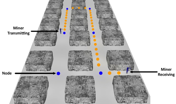
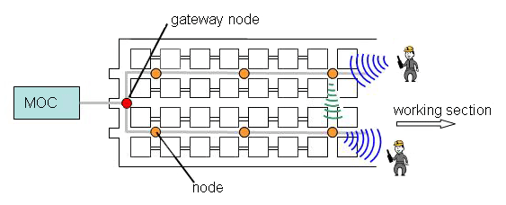
A mobile device, such as a hand-held radio, can access the network if it is within RF range of a wireless access point (WAP), another term for a fixed-position node. When a miner talks or sends a text message using his handset, a physical link is established with a nearby WAP. Using either wired or wireless links between nodes, the network routes the miner’s communication to the desired destination (address), either inside or outside the mine. A sample wireless mesh in a coal mine is depicted in Figure 2-17; the orange dots indicate the propagation of the signal between blue WAPs and finally to the hand-held radio receiver.
Node-based systems generally operate in frequency bands that do not require the devices to be licensed by the Federal Communications Commission (FCC) [47 CFR 15]. Being unlicensed though does not mean unregulated. The FCC has established rules which attempt to minimize the potential of the unlicensed devices from interfering with licensed operations, such as TV broadcasts. Because of the numerous devices that operate in the unlicensed bands, standards have been developed to increase the compatibility between systems operating in the same band. One organization that develops many of the communications standards is the Institute of Electrical and Electronics Engineers (IEEE).
Three types of node-based systems are being proposed for use in underground mines by various manufacturers: wireless local area network (WLAN), wireless fidelity (Wi-Fi) mesh, and ad hoc mesh. All of these systems operate by taking information from the sender’s radio, receiving it at an access node, routing it through the network, and retransmitting it to a recipient radio. How these actions are accomplished varies considerably among the systems.
2.3.1.1 WLAN Mesh Systems
The first system to be discussed is a wireless LAN or WLAN. WLANs are familiar as systems used in the home or office to allow a computer to wirelessly connect to the Internet as shown in Figure 2-18.
WLANs identify each computer on the network by a unique identifier called the Internet Protocol address (IP address). In a large network, the IP address is assigned by a centralized server. Each message contains two addresses: the sending (source) node, and the intended recipient (destination). The source node sends the information to the gateway node, and the gateway node then sends it to the recipient as shown in Figure 2-18.
WLANs typically use technology based on the IEEE 802.11b/g technology standard. This open standard allows equipment manufacturers to build devices that will be compatible with systems built to the standard, resulting in a proliferation of devices. In a normal configuration, WLAN uses standard Ethernet protocol (rules for sending messages) with wired connections between the nodes as shown in Figure 2-19. Thus the access link is wireless, and the backhaul links are wired.
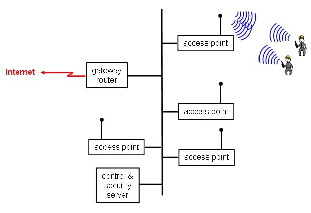
With the network arrangement shown in Figure 2-19, if one of the nodes should become inoperable, the remaining network should remain functional. Of course, if the communications bus is damaged, the whole network could be disabled. WLAN systems are not inherently robust, but can be made to be quite survivable if a fiber-optic ring topology is used as discussed in Chapter 4. Additionally, the WLAN standard provides methods to limit dependency on a central server for data applications; however, for voice applications a central server is required.
Another limitation of a WLAN system is the ability of the system to handle the mobility of a user. As the miner moves from the coverage area of one node to another node, the system must recognize that the source node has changed and redirect traffic accordingly. This process is sometimes referred to as handoff, with the system handing off the responsibility for a miner’s radio call or text message from one node to another as the miner moves. WLAN systems generally have difficulty properly handling mobility, particularly at speeds greater than walking, such as miners riding in vehicles in the mine.
In order to improve the survivability of these systems and to overcome some of the limitations, various manufacturers have implemented proprietary features in Wi-Fi mesh systems, discussed next.
2.3.1.2 Wi-Fi Mesh Systems
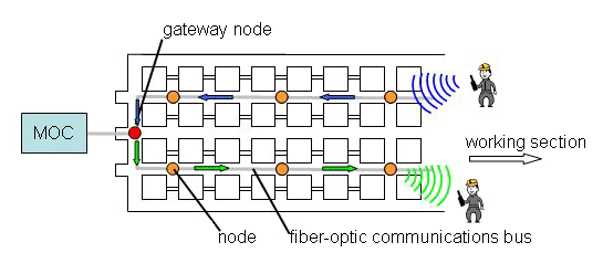
The second node-based system to be discussed is the Wi-Fi mesh system, which is a variation of the WLAN system. As with the WLAN system, Wi-Fi mesh systems use the same IEEE 802.11b/g standard for the access link, which allows the use of standardized devices; however, the backhaul links can be either wired or wireless. Another important difference is that the routing of traffic through the network is not dependent on a central server, but is handled by the individual nodes. These improvements are accomplished using proprietary techniques unique to each manufacturer, although standards have been proposed. Figure 2-20 shows a Wi-Fi mesh system with a fiber-optic backhaul. Notice that the communication from one miner to the other no longer has to pass through a gateway node.
Many of these Wi-Fi mesh systems rely on proprietary routing protocols that allow a given node to communicate through a particular subset of nodes, which allows the system to reconfigure itself if one node fails. However, in the event that the bus is cut or otherwise disrupted, the ability of the system to reconfigure itself is limited by the wireless range of the node. For the system to reconfigure itself, any given node must be in radio range of multiple other nodes, so a high node density (high degree of coverage overlap between nodes) has to exist for this type of redundancy to be implemented.
Neither the WLAN nor Wi-Fi mesh systems are considered ad hoc mesh systems (discussed next). The WLAN or Wi-Fi systems can be quite survivable if the system is designed with some overlapping radio coverage and the software that controls the nodes permits autonomous reconfiguration. Additionally, because of the operating frequencies for 802.11b/g systems, the range of the access link is typically limited to line-of-sight. Assuming comparable transmitter power, this leads to the need for more infrastructure in the mine for the same level of radio coverage as compared to some of the ad hoc mesh systems.
2.3.1.3 Ad Hoc Mesh Systems
The third node-based communications system to be discussed is the ad hoc mesh system, which communicates node-to-node through a network similar to Wi-Fi mesh systems, but with a few key differences.
Some of the characteristics that distinguish an ad hoc mesh system from a Wi-Fi mesh system are:
- The end user device (mobile radio) can serve as a mesh node, relaying network traffic from other radios on the network.
- Any node in the network can autonomously communicate with any other node that is within radio range and is not limited to a predefined subset of nodes within its range.
- Any group of nodes that are within direct radio range of each other can autonomously form a network without any dependency on a central server.
One example of an ad hoc mesh system is commonly referred to as ZigBee, which refers to the IEEE 802.15.4 standard. ZigBee is a true ad hoc mesh protocol and has the additional advantage of being able to operate in the 900 MHz range, which is the frequency for maximum radio range in most underground coal mines. However, ZigBee operates at low power and does not support voice communications.
NIOSH has funded the modification of a ZigBee-based mesh system so that compressed voice (modification of a voice message to reduce the required bandwidth) could be supported over the network while continuing to have the advantages of an ad hoc mesh. Compressed voice is a low-bit-rate form of voice communications that can be used over bandwidth-constrained systems. The advantages of this approach are:
- Full ad hoc mesh capabilities, which maximize the flexibility of extending and/or repairing networks.
- Low-bit-rate voice can result in an increased communications range, as was discussed in Section 2.1.1.
- 900 MHz operational frequency to improve the communications range of the nodes.
- Compressed voice may support future interoperability with TTE and MF systems, which may use the same approach.
2.3.2 Components
The primary component in a node-based network is, of course, the nodes deployed throughout the mine to provide wireless coverage. The nodes send and receive radio signals to extend the communications range between hand-held devices, which are another component of the system. The mesh network uses a variety of mobile devices such as hand-held voice-over-Internet-Protocol (VoIP) phones, laptop computers, tracking tags, and text communicators. The nodes link with other nodes to form a wireless or wired network throughout the mine.
Nodes may be called by other names such as mesh points (MPs), access points (APs), or wireless access points (WAPs). Figure 2-21 shows an example of a wireless node. Under normal operation, the nodes require power from an external supply. Thus, they must be located near electrical power wiring. In an emergency, when main power is unavailable, the nodes can operate from a backup battery. A node may be about the size of a lunch box and has an external antenna.
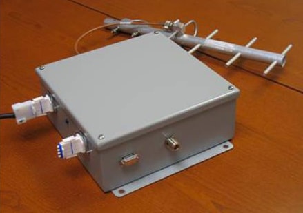
In the mine operations center (MOC), there would likely be a computer server and display monitor to show information on the network performance and system diagnostics. There also might be a display of a mine map showing the node locations and operational status of each.
Figure 2-22 depicts an example of a block diagram for a wireless mesh network. Solid lines indicate wired communications paths, and broken lines indicate wireless communications paths. In the diagram, the nodes have wireless interconnections, but they could also have wired connections to other nodes.
Some mesh networks identify one node as the gateway (or root) node. This is the point where the wireless network transitions to a wired connection to the MOC aboveground. Thus, all of the network traffic into or out of the mine flows through the gateway node.
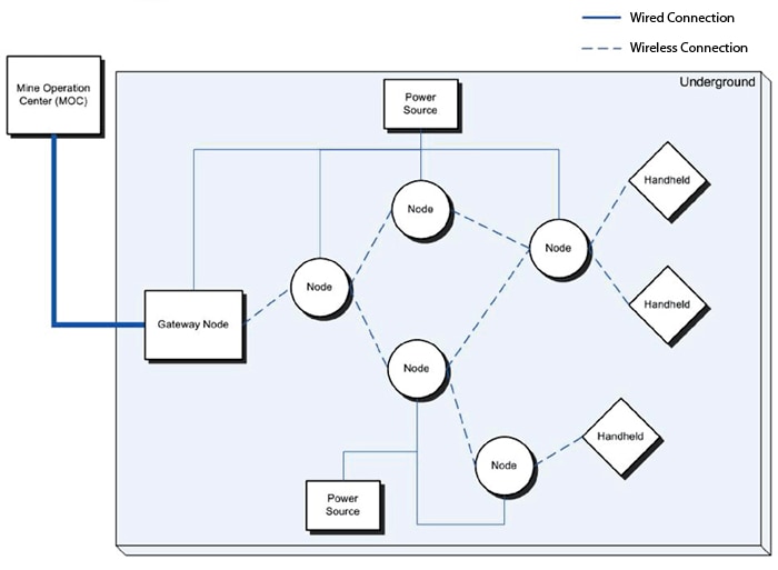
2.3.3 Transmission Media
The communications between two miners talking over their hand-held radios involves a number of intermediate physical links depending on how many nodes are included in the route, as shown in Figure 2-23. The first link is through the air from the sender’s radio on the left to the node labeled 1. The second link is through the air from node 1 to node 2. The third link is through the air from node 2 to node 4. The final link is through the air from node 4 to the radio on the right. The signal has undergone three hops, i.e., the signal has passed through three intermediate devices (nodes).
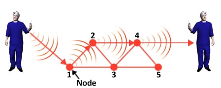
The link budget analysis is applied only to the access link of Figure 2-23. The analysis begins with the transmit power of the sending radio (Pt) on the left axis in Figure 2-24. Gt represents the antenna gain (assuming it is positive) of the sending radio (transmitter), which adds to the transmit power. There is a path loss (Lp1) as the RF signal propagates through the air to node 1. The node has a receiving antenna gain of Gnode, which adds to the received power, resulting in Pr at the receiver. The manufacturer should be able to supply most of the values used in this link budget analysis.
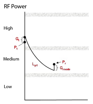
2.3.4 Network Operations
One of the advantages of a node-based communications system is its flexibility—it can use any of the network topologies available. To obtain continuous radio coverage in the long entries that are typical in a coal mine, certain topologies become more practical than others. Figure 2-25 shows a node-based linear network. Such a network could provide continuous coverage in an entry.
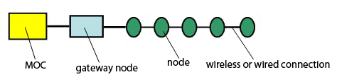
Should one of the nodes in Figure 2-25 fail, all communications inby the failed node would be lost. One way to increase the system survivability would be to have the nodes close enough so that the RF range of each node extended beyond its upstream and downstream adjacent nodes to the node beyond. This approach increases the system cost, because more nodes would be required to cover the same length of entry. It is a viable method for adding redundancy to the system, although if the node failure is due to a roof collapse, the RF signal is unlikely to propagate around or through the debris.
Figure 2-26 shows a partial mesh network in which radio coverage is provided in two parallel entries and the nodes (blue dots) can communicate down crosscuts.
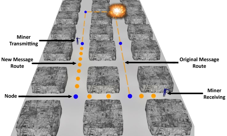
The original message route in Figure 2-26 followed the dashed line through the node in the upper right corner. An accident caused the node in the upper right corner to fail. In a self-healing mesh network, an alternate route (assuming one exists) will be determined as shown by the orange dots. This redundant path increases the survivability of the network.
Some manufacturers’ nodes require that each node preprogram the allowable backhaul links that form the network topology. This is sometimes termed a constrained mesh network. The nodes autonomously detect network failures and switch traffic through predetermined backup routes. Because the routes are predefined, the fail-switch-over dead time (outage time) can be very short.
In contrast, some manufacturers’ nodes automatically and autonomously establish the network, because the equipment has the capability for self-configuring and self-healing. An ad hoc or self-configuring network will detect the presence of a mobile node, possibly a hand-held radio, as it comes within RF range of the network, and it will incorporate it automatically as part of the network. A self-configuring network automatically identifies the links that are available from each node and uses an algorithm to connect each node to the network using a subset of the available links. If an accident should disable a node or nodes, the self-healing feature will cause the network to reconnect all possible surviving nodes by other available links. There is a delay associated with the node switching over to other routes that is longer than in the constrained mesh network case. Another possible delay occurs when traffic in a mesh network travels over multiple wireless hops to reach its destination; the throughput may be severely reduced compared to the rate of each hop alone. In addition, passing through multiple nodes may delay data packets. This added delay, called latency, defined as the amount of time it takes a data packet to be transmitted end-to-end across the network, can be especially harmful to real-time communications such as voice.
Products are available that link some or all of the fixed nodes of the network with wired or fiber-optic cable connections. To the extent that wire or fiber-optic connections are used, these networks may have limited or no ability to self-configure and self-heal and must be treated differently when analyzed for survivability.
2.3.5 System Implementation
Node-based communications systems offer the potential of easy-to-implement, redundant message routes, which increase the survivability of the system. One way to achieve redundancy is with a wireless mesh network with nodes installed in parallel entries, such that there are backhaul links connecting nodes in different entries through adjoining crosscuts. Such a scheme permits redundant communications routes by providing a route that can bypass a failed node and still reach the MOC or other hand-held or portable radios.
As discussed in Section 2.3.1, the backhaul connections can be wireless or wired. Although wired connections increase the amount of infrastructure for the system, burying the connecting cables protects them from roof falls and explosive forces. Figure 2-27 shows a working section where a roof fall could block a passageway sufficiently that an RF signal could not pass, even though there is no damage to the nodes on either side of the fall. A buried cable might survive the roof fall without interruption of service - a possible advantage of having wired connections of nodes.
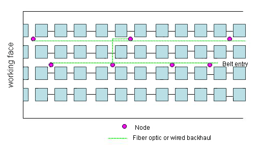
There are other approaches to providing redundancy with node-based systems. Many mines have existing leaky feeder systems. Bridge nodes can couple node-based RF communications installed in a separate entry to the leaky feeder cable. The bridge node converts the RF signal of the mesh to frequencies that are compatible with the leaky feeder system. There is hardware and software in the MOC that recovers and interprets the mesh digital signal as received on the leaky feeder.
It may be useful to implement a node-based system in a working section. It is relatively easy to extend the coverage of the node-based system as the face advances (Figure 2-28). Node-based systems can also provide electronic tracking information, which is required in the working sections (see Section 3.3). A bridge node can interconnect the node-based system in the working section to the system in the main entry. The bridge node permits the two systems to communicate with each other. In this case, the backhaul to the MOC is through some other communications system, such as a leaky feeder system, but the backhaul could also be node-based.
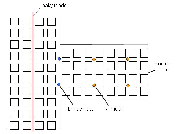
Each node does require mine AC power for normal long-term operation. When the mine power is either disrupted or turned off (as during an emergency), each node needs a backup battery to provide power for continued operations. Typically, the battery might provide power for 24, 48, or 96 hours, depending on the MSHA requirements.
2.3.6 Maintainability and Inspection
Maintenance for the node-based system’s central computer will be similar to normal maintenance provided for all computer-type functions (e.g., cleaning, antivirus, security, memory and file backup, software updates). Some system providers will provide network software updates that are downloadable directly through an Internet connection. Because mine maps will have to be updated regularly, systems that provide map displays should provide utility programs to allow mine personnel to easily load updated maps. The system will run initialization, diagnostic, and database applications for adding and monitoring underground components, and will typically provide offsite remote monitoring capabilities through an Internet connection. To allow for quick identification and replacement of failed underground components, network monitoring should be continuous. Node and antenna replacement is easy. However, failed backhaul cabling may require replacement of long lengths of cable or careful repair procedures. Node backup batteries have a limited lifetime; therefore, network diagnostic capabilities should include battery status monitoring. Periodic battery capacity tests ensure that the batteries will function during emergencies. Power supplies must be disconnected to check battery backup switchover and capacity, and redundant communications paths should be periodically tested by powering down nodes to test the network reconfiguration capability.
2.3.7 Performance and Limitations
A number of equipment and environmental factors influence wireless node coverage distance or range. Transmitter power, antenna gain, receiver sensitivity, data rate, and frequency are the primary factors related to the node-based equipment, and the link loss budgets account for these factors. In addition, entry dimensions, bends, elevation changes, and obstructions will further limit wireless coverage.
The U.S. Bureau of Mines (USBM) sponsored several radio propagation studies during the 1970s. NIOSH has made these studies available for download through the NIOSH Mining internet site on the Downloadable Mining Publications page.
One study that is particularly relevant to modern node systems involves a theory of propagation of UHF radio waves in coal mine tunnels [Emslie et al. 1975]. This study proposed that mine entries act as waveguides for frequencies in the UHF range. Figure 2-29 was adapted from a figure in Emslie et al.’s paper, and is based on a coal mine entry 4.3 m wide by 2.1 m high (14 ft wide by 7 ft high).
![Figure 2-29. UHF propagation path loss modeling [adapted from Emslie et al. 1975].](../../../UserFiles/content/emergencymanagementandresponse/commtracking/commtrackingtutorial2/2-29.png)
The curve includes the insertion losses for the transmitter and receiver antennas, which result from the mismatch of the antennas to the fundamental mode of the waveguide (mine entry). The increase in path losses as the frequency increases is due to energy lost in the interaction of the UHF wave with the walls, floor, and roof. The increase in path loss at the low frequency end of the curve is due to the wavelength approaching the dimensions of the entry, making UHF propagation more difficult. The minimum in the propagation loss in the 800 to 1,000 MHz range is sometimes referred to as the UHF propagation "sweet spot" for typical underground coal mine entries.
Systems operating at 900 MHz have demonstrated coverage that is not line-of-sight down a parallel entry for several crosscuts. Entry obstructions will absorb or reflect UHF signals, diminishing wireless coverage. Coverage distances in conveyor belt entries will generally be less than coverage in open entries due to the belt structure. Bends or changes in elevation that block the line-of-sight will also generally reduce wireless coverage range. Large vehicles will partially block UHF signals, and adequate fade margin should be factored into UHF backhaul link budgets to minimize the impact. Observations of concrete stoppings have shown they will attenuate UHF signals somewhat, approximately 10 to 15 dB in the 900 MHz range. Temporary metallic stoppings will reflect much of the incident signal so that transmissions through metallic stoppings will have large attenuations. In contrast, metallic surfaces can be used as reflectors to direct UHF signals around corners.
Overall network coverage will be limited by the total latency of the system. Latency increases with the number of hops through a network of nodes. Video or voice transmission requires that the delay (latency) through the network be consistent for the duration of the transmission, but short enough so that it is not a nuisance. Main entries of large mines can use long-distance fiber-optic links to reduce the number of hops and associated latency. Latency is much less of an issue for low bandwidth data transmissions, such as transmitting text [Emslie et al. 1975].
WLAN or Wi-Fi systems support commonly available VoIP phones. VoIP phones require an intermediate node; they do not support phone-to-phone (i.e., peer-to-peer) operation. True ad hoc ZigBee mesh networks will not support VoIP phones; however, they may support communications devices that can also communicate independently of the network (peer-to-peer communications). As mentioned previously, these ad hoc mesh communications devices may also function as nodes, relaying messages from other communications devices that may be out of network coverage. One advantage of WLAN or Wi-Fi networks is interoperability with a wide variety of commercially available equipment. However, very few of these networks are currently MSHA-permissible. This presents a safety concern even in intake air courses during a fan stoppage or mine emergencies when the ventilation system is compromised.
Node-based user communications devices can also serve as tracking devices. The system can identify which node is the access node for a particular user device. The system functions much like an RFID tracking system in this respect, with the communications device acting as a tag and the access node acting as the reader. If a communications device is in contact with one node, the location accuracy is generally the radio range of the specific device or node, whichever is less. Techniques such as received signal strength indicator (RSSI), time difference of arrival (TDOA), or time of flight (TOF) can estimate a more accurate location, but may require the radio to be in contact with multiple nodes simultaneously.
Node-based communications systems offer the potential of easy-to-implement, redundant RF message routes, which can increase the survivability of the system. As discussed in Section 2.3.2, the backhaul connections can be either wireless or wired. Segments of communications systems can be installed between multiple portals to the surface. For these situations, a linear topology (either wireless or cabled) may be implemented with both ends of the segment installed in separate portals to provide a redundant backhaul link to the surface. Segments of communications systems inby the last access to the surface may employ different topologies to achieve full redundancy. The following discussion considers two inby cases: wired (or fiber optic) and wireless backhaul links.
Figure 2-30 shows a partial mesh network with wireless backhaul links. Dashed lines indicate the wireless links. The node layout (depicted as blue dots) is such that failure of any one node will not cut off communications to the surface inby the failed node. Node placement in different crosscuts of adjacent entries may enhance survivability during emergencies. Node-based systems operating at 900 MHz have been observed to provide non-line-of-sight connectivity between nodes in adjacent entries to within a few crosscuts. Antenna cables can be used to place antennas in adjacent entries, such as those separated by metallic stoppings. Catastrophic events may disable multiple nodes in adjacent entries, isolating clusters of inby nodes. True ad hoc mesh networks allow for automatic reconfiguration of isolated node clusters, establishing a new network within the isolated cluster.
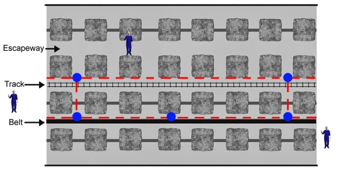
Figure 2-31 shows a WLAN or Wi-Fi network with fiber-optic backhaul links in a working section. A modified ring topology formed from two adjacent linear spurs supports bidirectional backhaul links for redundancy. The connection forming the loop between two spurs can advance as the face advances to prevent isolation of multiple nodes extending to the face area. The connection forming the loop may be wireless. Protecting the wire or fiber-optic cable in damage-prone areas such as in front of seals may help to enhance network survivability. An ad hoc mesh implementation may allow isolated nodes to reform a network.
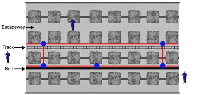
Each node does require mine AC power for normal long-term operation. When the mine power is off (as during an emergency), each node needs a backup battery. User communications devices will typically operate for at least 12 hours. If an emergency occurs at the end of the shift, there may be only 4 hours or less of battery reserve. Manual shutoff or spare handsets can extend operation over a longer period. MSHA permissibility requirements for some types of handsets may prohibit battery replacement where excess methane is present.
2.4 Secondary Communications Systems: Medium Frequency Systems
2.4.1 Medium Frequency (MF) Description
Medium frequency (MF) communications systems are so named because they operate in the 300 kHz to 3 MHz band, most typically around 500 kHz. MF systems are characterized by their particular method of electromagnetic wave propagation. The MF radio waves parasitically couple (i.e., they attach themselves) to nearby existing metallic conductors within the mine entry. In other words, the conductors act as distributed antennas, able to receive and transmit MF signals as shown in Figure 2-32. The conductor also acts as part of a transmission line to transport the MF signal. The signal radiates off the conductor as it propagates, so essentially the conductor behaves as a very inexpensive leaky feeder cable. The conductors, for example, can be pre-existing mine telephone wire, water pipes, or leaky feeder cable. Both solid copper twisted-pair phone wire and leaky feeder cable serve as excellent conductors for propagation of MF signals because they are continuous. Other possible conductors include power cables, armored cables, data cables, conveyor structures, metal piping, wire-core lifelines, or inexpensive wiring specifically installed for MF communications.
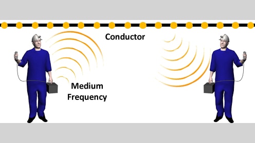
An example of an MF radio consists of a hand-held speaker/microphone with a connecting cord to the transceiver, which is connected to either an external ferrite or a bandolier-style loop antenna, or an integrated package that includes the antenna and batteries (Figure 2-33). An MF radio is generally considered to be a secondary communications system, except possibly when used in small mines. It is more accurately described as a man-portable radio because it is significantly bigger and heavier than a typical hand-held UHF or VHF radio. Given the size and weight of the MF radio, a miner will likely not wear it continuously. One option is to carry the MF radios to a working area and place them nearby so miners have ready access to them. Alternatively, the MF radio might be used mainly for emergencies, perhaps stored in mine rescue chambers.
![Figure 2-33. Miner carrying a medium frequency (MF) radio. [Kutta Radios 2011]](../../../UserFiles/content/emergencymanagementandresponse/commtracking/commtrackingtutorial2/2-33.png)
MF systems are useful for providing alternate, and what are more likely, survivable communications paths from a working section. The most diverse paths would be through existing boreholes or separate entries other than the main entry. Boreholes offer a direct path to the surface in which a conductor can pass and provide communications to the surface. Continuous metal-cased boreholes can be used to carry an MF signal. The MF signal can either travel directly to the mine operations center (MOC) or be converted to UHF or VHF using a bridge node (discussed later in this section) link to a hand-held radio. MSHA-approved MF systems (e.g., Kutta Radios DRUM™ Mine Radio 100P and Mine Radio Repeater 100R) that are currently available for coal mine applications are analog voice communications systems. An MF bridging device exists that is able to interconnect MF with higher frequency systems like UHF or VHF. The device is called a bridge repeater, up-down frequency converter, cross-band repeater, or bridge node. It can convert RF signals received in one frequency band to RF signals in a different frequency band. For example, the bridge node can down-convert signals received in UHF to signals transmitted at MF, or conversely, received in MF and transmitted at UHF. Thus, the bridge node acts somewhat like a conventional radio repeater, except that it retransmits the signal it receives at a different frequency.
The band conversion repeater can be used to create a hybrid system of unique capabilities. Figure 2-34 is an example of how the bridge node is used. The sender on the left communicates with the bridge node using a hand-held UHF radio. The bridge node converts the UHF message to MF, which couples to a nearby metallic conductor. Another bridge node picks up the MF message from the conductor and then retransmits the message at UHF for the UHF receiver radio on the right. Thus, the UHF radios plus the MF repeaters permit communications between UHF radios, like the Kenwood TK 290/390 or the Motorola HT750, without any of the usual UHF infrastructure. The two UHF/VHF radios do need to be tuned to the same channel.
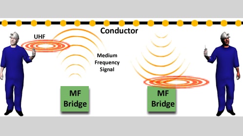
2.4.2 MF Components
The assembly of an MF radio system requires very few components (Figure 2-33). Man-portable MF radios (speaker/microphone, radio, batteries, antenna) and continuous metallic conductors are all that is necessary to establish a communications system. Unlike leaky feeder systems, there are no line amplifiers for the analog MF system, and hence, there is a limit to the maximum separation between sender and receiver. A representative maximum separation distance is in the range of 3 to 6 kilometers (about 2 to 4 miles), but distances exceeding 8 kilometers (about 5 miles) have been observed. Finding or installing suitable conductors in a mine involves mine-specific considerations. The best way to determine whether a conductor will work is to simply try communicating some significant distance using the conductor and two portable MF radios. The best propagation is achieved with multiple insulated conductors in the entry, with a single end of one of the conductors tied to an appropriate electrical ground. Properly resistance-terminated and grounded solid copper or other low-resistance wires will help to increase the distance an MF signal can propagate. Three-phase power cable and shielded power cable can be used to transmit the signal as well, although electrical noise can interfere with the MF signal while the power is on.
One advantage of transmitting MF signals on the copper core of power cables is that they frequently remain intact after a mine disaster due to the large diameter of the conductors, thus enhancing the survivability of the communications system. Wire-core lifelines are another option for allowing MF signals to propagate along an escape route. Lifelines offer a definite advantage in that the miner and/or rescuer are likely to be extremely close to the conductor most of the time, which will enhance the MF radio performance.
2.4.3 MF Transmission Media and Link Budget Analysis
Figure 2-35 shows the three parts of a physical link involved in establishing communications between a sender on the left and a receiver on the right using an MF communications system - namely air, conductor, and air again.
Link 1 includes the losses from the transmitter, through the transmit antenna, propagation through the air, and coupling to the conductor. Figure 2-36 schematically shows the power losses or gains, in dB, starting with the transmitter power (Pt). The transmit antenna gain (Gt) is shown as a power decrease or negative gain because the antenna dimensions are comparable to the largest dimension of the briefcase shown in Figure 2-35; hence, the antenna is much smaller than the wavelength in the MF band. Therefore, the antenna is very inefficient. Path loss through the air (Lp1) and the RF coupling loss from the air into the conductor are shown in Figure 2.36.
Link 2 involves the MF propagation along the conductor. As in the leaky feeder cable, there is an attenuation of the power of the MF signal as it progresses along the conductor, although the MF attenuation is typically much less.
Link 3 accounts for a potential loss in power in coupling the RF signal from the conductor to the air. Then there is the path loss through the air (Lp2) and the negative gain of the receiving antenna (Gr). The power at the receiver (Pr) must exceed the receiver signal-level threshold to create a viable communications connection. The communications equipment manufacturer can provide the actual values for the various link budget parameters.
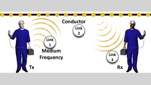
sender (Tx) and receiver (Rx).
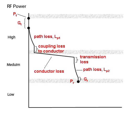
2.4.4 MF Network Operations
The analog MF systems that are commercially available transmit using a very narrow bandwidth that typically allows only one channel for communications. When a sender keys his/her microphone to talk, the sender is broadcasting to all radios within MF range. Even though many users can communicate using this system, it is not a network. There are no programmable components to control the routing of message traffic. Further, there are no analog repeaters to extend the range necessary in large mines.
In contrast, digital MF systems which are presently under development will have the intelligence, control, and switching capability built into the bridge nodes (i.e., MF/UHF or MF/VHF nodes), as discussed in Section 2.4.1, to perform message routing similar to node-based system networks, as discussed in Section 2.3.
2.4.5 MF System Implementation
As mentioned in Section 2.4.1 the principal use for MF communications systems is most likely to be for secondary communications systems and/or alternate communications paths. MF radios can be a primary communications system for small mines. Either metallic conductors that already exist in mine entries could be used, or inexpensive conductors could be installed specifically for MF communications. In addition, it is also possible to build in redundancy using conductors in parallel entries.
Miners would carry MF radios to their working areas to provide their communications connections to other miners and to the surface. MF signals will couple to conductors that have been buried in a trench to increase the survivability of the conductor.
UHF radios and the MF/UHF bridge nodes can be used to extend leaky feeder coverage into a working section. Figure 2-37 shows a worker near the working face. The worker communicates with a UHF radio that links to the MF/UHF bridge node. The bridge node receives the UHF message, converts it to MF, and couples the signal to a nearby conductor. The MF signal travels down the conductor until a bridge node picks up the signal and then retransmits the message in UHF to be linked to the leaky feeder cable.
The miner at the working face could also be issued an MF radio. The power cable to a continuous miner is a good conductor for MF signals. The MF signals would be carried back towards the main entry where a bridge node would capture the MF message and retransmit a UHF signal to couple to a leaky feeder backbone system. The rugged continuous miner power cable will frequently survive a roof collapse, thereby providing an inherently hardened communications line.
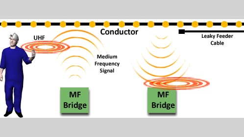
There are also niche applications for MF radios. MF radios could be installed on a man trip to provide a redundant communications system if conductors are present in the entry. MF radios could be stored in caches in critical areas or stored in rescue chambers for use during emergencies. The assumption is that some conductors may survive the event and present a continuous path for MF signals.
The proximity of the MF antenna to the conductor is very important to maintain good communications. A person, located relatively far from the conductor, can often receive the MF signal, but may not have the ability to respond, i.e., because a communications link cannot be established in the reverse direction. This appears to be due to the difference in signal-to-noise ratio (SNR) on the conductor when the transmitter is close to the conductor (high SNR) compared to the return communication from the MF radio that is further from the conductor, and hence has a low SNR on the conductor. It is highly recommended that the user place his radio as close as possible (although no hard-wired metallic connection is needed) to the conducting medium to achieve the best coupling of the signal to the conductor.
It has been mentioned in the paragraphs above that noise sources can affect the ability to communicate using MF. RF noise sources that can generate frequencies in the MF range include 60-Hz power harmonics, belt-drive motors, power centers, pumps, continuous miners, and longwall equipment. Other equipment that could interfere with MF communications could be powered haulage vehicles, and very large DC drives, especially if they experience large changes in power demand. These types of equipment cause interference by producing current or voltage fluctuations at frequencies in the MF band which combine with the MF communications signals, making it difficult to separate out the communications information. The interference can introduce static, distortion, or completely overwhelm the MF signal. The interference typically occurs in the vicinity of the noise source as most low-frequency noise sources do not propagate very far along the same conductor as the MF signal. The best solution to correct this problem is to add separation distance between the conductor, the MF radio, and these noise sources. In some cases, distances as short as a meter may dramatically decrease the effects of the noise source.
2.4.6 MF Maintenance and Inspection
Because only a few components are needed to operate an MF system, the system is not very complex. The factors that most influence performance are the conductor configuration and the proximity of the radio to the conductor. Because all conductors in an entry near an MF radio can participate in propagating the signal, some trial-and-error testing is needed to determine signal strength at strategic locations throughout the mine. One basic method of determining signal propagation characteristics is to periodically check the quality of the communications. If conductors or conductor connections have been changed, the system may not work as originally intended. If the mine has many miles (kilometers) of conductors, there is a reasonable chance that a conductor path will be altered or removed.
Inspections that should be routinely made of a simple MF system are the MF bridges, hand-held radios, and the conductors between them. Simple voice spot checks should be performed at strategic locations to ensure that the radios, bridges, and conductors are properly working, preferably at the beginning of each shift. More complex digital MF systems may be able to diagnose problems related to coverage and unit functionality, but the limited bandwidth of the system may restrict this operation. Analog voice systems are easier to install and use than digital-based systems, but do not offer much capability in troubleshooting.
Battery maintenance is similar to other battery-operated systems. The battery charge and health of the portable MF radios can be verified at the start of each shift before taking the radios underground. The fixed position MF bridges will be powered by mine power until an emergency, in which case, they may revert to battery backup power if the mine power is shut down. It is recommended that the fixed position bridge includes some type of indicator that shows the status of the battery’s charge.
2.4.7 MF Performance and Limitations
The radio signal coverage of an MF system depends on a number of factors. The communication range of two MF radios in free space can vary with the transmitted power level, but typical surface ranges are usually up to 30 meters (100 feet). However, in the presence of a metallic conductor, the MF signal can propagate for 3 to 6 kilometers (2 to 4 miles) due to parasitic coupling. If conductors are properly configured, MF signals can travel on many different conductors throughout the entire mine.
There are two main factors that strongly influence the communications range of an MF system. The first is the overall conductor transmission range, which is the distance that the MF signal propagates along the conductors. In order to ensure the maximum coverage along a conductor, proper grounding and terminating are important. Note that for existing conductors like power cables, this may not be possible.
The second consideration is the separation distance between the MF radio and the nearest conductor. The coupling between the radio and the conductor decreases dramatically with an increase in separation distance. The closer the MF radio is to the conductor, the stronger the coupling to the conductor. Stronger coupling results in a larger signal on the conductor, hence a greater SNR and a greater likelihood of a signal of adequate amplitude reaching the intended radio receiver.
Due to the higher power requirements needed to generate a magnetic field through the antennas (loop or ferrite core coil), the battery life for an MF radio is less than that of a UHF or VHF radio. Batteries for stationary MF bridges can be larger and heavier because portability is not a concern. If a mine accident occurs, the primary communications system may become inoperable. If the miners inby the accident have an MF portable radio, it may provide an alternate, secondary communications mechanism by using whatever conductors are nearby. If the accident occurs between the escape route and the working face, it would be best to try the MF radio using whatever conductors are nearby.
2.5 Secondary Communications: Through-the-Earth Systems
2.5.1 Description of Through-the-Earth Systems
Most electromagnetic waves can only penetrate short distances into or through the earth. However, it is possible for ultralow-frequency (ULF), long-wavelength EM waves to penetrate several thousand feet through the earth’s strata. Such ULF systems are called through-the-earth (TTE) systems because they have the potential to provide wireless communications between underground and surface personnel without intervening infrastructure, perhaps more closely meeting the intent of the MINER Act of 2006. With less infrastructure than traditional communications systems require, TTE systems are more likely to survive an underground explosion and to provide a communications link to the surface for trapped or escaping miners.
TTE systems typically operate between 72 Hz and 4,000 Hz. These frequencies result in wavelengths between 70 and 3,200 km (45 and 2,000 miles) in free space. Portable communications systems operating in the VHF or UHF band often use half-wavelength dipole or quarter-wavelength whip antennas to achieve high transmission efficiency. Note that the transmission efficiency is high for antennas with linear dimensions that are a major fraction of a wavelength. In contrast, TTE antennas are very inefficient because of their extremely long wavelengths. This means that only a small fraction of the transmitter power is actually radiated from the antenna.
The path for the TTE transmitted signals can be either vertical (through the earth or overburden) or horizontal (through the coal seam). TTE systems generally operate as half duplex systems which provide communications in both directions, but in only one direction at a time (not simultaneously). They may provide voice in real time, voice or text messages, or emit a periodic beacon signal, which can be detected on the surface and which allows rescuers, typically on the surface, to estimate the underground location of the transmitter. Each of these modes is characterized by different signal transmission rates. For example, data rates as high as 2.5 kbps permit real-time digitized voice, but rates as slow as 10 bps only allow text at one keystroke per second. Obviously, real-time voice is desirable, but TTE transmission range is affected and limited by data rate, as well as by other factors discussed below.
Factors that affect TTE signal transmission include the frequency, transmitter power, and nature of the overburden strata such as electrical conductivity, depth, and any geological variations that can alter the overburden electrical properties. The reception of a transmitted signal is also affected by the presence of electrical noise, both underground and on the surface, both natural and manmade. The ability of the system to communicate is dependent upon the remaining energy of the transmitted signal, after attenuation through the earth, being sufficient to be distinguished from the noise at the receiver location. Finally, the antenna configuration, e.g., wire loop, ferrite core coil, or linear wire line, can impact transmission and reception.
It is known that the lower the frequency of a transmitted signal, the lower the signal attenuation through the earth. However, at ultralow frequencies, data transmission rates are limited and only text messages or preprogrammed messages may be possible. The lowest practical rates generally allow the greatest depth penetration and are typically used to generate beacon signals underground. TTE beacon signals can be detected by rescuers on the surface at long ranges for which data and voice transmissions are not possible. The beacon signals help determine the approximate location of the transceiver underground.
Given these performance limitations, it may be desirable to have multiple transmission frequency capabilities to optimize TTE range and mode for a given set of geological conditions. Transmission range is proportional to transmitter power. However, when the transmitter is used underground, consideration must first be given to the safe use of electrical equipment in potentially explosive atmospheres. Consequently, transmitter power underground must be limited as required by MSHA approval regulations.
Surface TTE antennas are generally not restricted in their physical size or transmitting power. They may theoretically consist of large loops of wire, thousands of feet in circumference, which encompass most of the mine. Generally, the surface antenna should be directly over and encompass the areas of the mine needing coverage, such as mine refuge chambers. However, from a practical standpoint, they may likely be limited in size by the terrain and by limited access to property above the mine. Note that over a kilowatt of transmitting power may be used on the surface in order to transmit a strong signal to the underground environment. Some TTE systems currently under development have significantly smaller diameter loops that use multiple turns of conductor and transmit at much lower powers, some as low as a few watts.
The TTE receiving antenna may incorporate ferrite-core windings to conserve space for portability. To optimize antenna coupling, and consequently signal transmission, both sending and receiving loops (or windings) should be oriented in the same direction (Figure 2-38). Multiple ferrite windings may be placed in an X-Y-Z axes orientation for receiving antennas. Antenna outputs can then be added vectorially to obtain a resultant signal. Underground TTE transceivers can be used for communications to the surface or underground and from point-to-point (horizontally) within the mine. The transceivers may be transportable or in a fixed location, however they must be limited in power (MSHA intrinsically safe or permissible requirement) to ensure safe operation in potentially explosive atmospheres.
NIOSH funded multiple industrial TTE development projects to investigate the feasibility of applying various types of TTE technology to mining. All contracts resulted in the development of prototype or preprototype systems. Varying system features include both magnetic and electric field sensing, loop and line antennas, digital and analog processing, noise filtering and cancellation, and direction finding. All systems have been evaluated at various commercial underground mine sites during development.
As mentioned earlier, the underground antenna may be smaller for portability and may operate at less power to be MSHA-permissible. In one TTE system, the receive antenna is worn by the miner and is integrated with the miner’s cap lamp. When a message arrives, the miner’s lamp will flash. In this system, the communications are text only and travel in one direction only—from the surface to the underground miner. Unfortunately, personnel on the surface receive no indication that the miners have received their message.
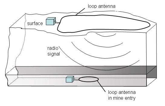
In another TTE system concept of operations, the miners deploy the underground antenna only when there is an actual emergency. The wire and associated transceiver equipment is worn on the belt of the miner or stored in a cache in a suitcase-sized enclosure. During an emergency, the miner may wrap the wire around a mine pillar to form an antenna. The structure of a rescue chamber can also incorporate the antenna. Two-way communications are possible with both text and voice messaging at depths exceeding 300 m (1,000 ft). Greater depths are generally associated with lower data rate communications such as text (compared to voice).
In another concept of operations, both TTE communications systems are underground. Similar to the concept shown in Figure 2-38, the trapped miners deploy one TTE system. The rescue workers bring in a second TTE system to establish communications horizontally with the trapped miners. Figure 2-39 demonstrates the concept.
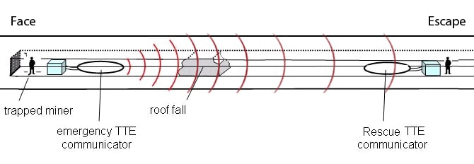
As was mentioned earlier, a TTE system cannot be used as a primary communications system for normal mine operations due to limited coverage and portability constraints, and low data transfer rates. At the ultralow frequencies of operation, it can take several minutes to transfer a text message. In addition, there are many sources of EMI and/or RF noise, e.g. spurious voltage signals, at low frequencies that make it difficult to separate out the message. Fortunately, in an emergency in which the underground power is off, the EM noise underground is decreased dramatically. The same is not true on the surface though, making it difficult to extract the message received from underground from the EM noise at the surface. However, the main advantage of a TTE communications link is that it is highly survivable and, therefore, is likely to play a significant role as an emergency alternate or secondary communications path.
2.5.2 Components
TTE systems consist of very few components. The simplest system, which only delivers messages from the surface to the underground miners, consists of a surface transmitter and one or more underground receivers. The surface transmitter has a power source, a modulator (a device for encoding the message into an RF signal), loop antenna, connecting cables, and a computer for entering messages. The TTE underground receiver has a loop or ferrite-core antenna, a demodulator to decode and display the message, and a power source (typically a battery) to power the system. The antenna could be just a spool of wire the miner lays on the mine floor to form a loop.
If the system provides two-way communications, the surface and underground units would both be transceivers (a combination of transmitter and receiver). Typically, different antennas are used for transmitting and receiving. The TTE electronics must be capable of both encoding and decoding messages.
2.5.3 Transmission Media
The earth (overburden) is the main transmission medium for TTE systems. The electrical properties of the intervening earth strongly affect the propagation of EM waves through the overburden of a mine. Significant changes in electrical properties between consecutive strata may cause a portion of the propagating RF energy to reflect at the interface, decreasing the strength of the signal that ultimately reaches the receiver.
The link budget analysis begins with the transmitter power (Pt), which could be on the surface or underground. The qualitative analysis in Figure 2-40 is the same whether the transmitter is on the surface or underground, but the quantitative analysis may have different numbers for the transmit power on the surface compared to transmitter power used underground. There is a decrease in power for the negative gain of the transmit antenna (Gt) followed by the path loss through the earth (Lp). This is then followed by the loss of the receiving antenna gain (Gr) to arrive at the received power (Pr). If there are cables connecting the transmit and receive antennas to their respective electronics, these cable losses would be in addition to the antenna gain losses. The communications equipment manufacturer can supply the actual values for the various link budget parameters.
2.5.4 Network Operations
Based on discussions in the previous sections on TTE, it is clear that the TTE system does not require network infrastructure to extend the communications range. Only one link through the earth is necessary between the sender and receiver. As is shown in Figure 2-39, there may be instances when an additional TTE system underground, acting as a repeater, would be helpful. For example, if the mine operators did not have access to all surface areas directly above the working sections, it may be advantageous to put the surface TTE system in a fixed location with another TTE system directly under it within the mine. The underground TTE system could then act as a repeater for any other underground TTE system that the miners might set up during an emergency.
The miners could periodically move their TTE units as the face advanced or if operations moved to a different area of the mine. The repeater and surface TTE units would remain in fixed locations. Some preplanning is required to coordinate the use of multiple TTE devices to avoid signal collisions. Most TTE devices do not detect whether another device is transmitting at the same time they are trying to transmit; this is called collision avoidance or blocking. TTE devices can only transmit or only receive at any given time and hence, if a TTE device is transmitting, it cannot detect or receive an incoming signal.
2.5.5 System Implementation
The most likely use for TTE systems is in mine emergency situations only, with other technologies providing the primary communications for daily operations. Even though the system is intended for emergency operation only, it would be prudent to periodically check that TTE communications can be established between two locations.
One manufacturer’s system requires a very large loop on the surface for the transmit antenna. The projection of the surface loop onto the mine workings encloses the area covered by the system. Because the surface loop can be very large, up to 12 km (7.5 miles) in length, it would be prudent to install it ahead of time, rather than immediately after an emergency. This system provides one-way communications, typically text messages, from the surface to miners. The miners receive the message in a personal receiver that they wear, usually powered by the miner’s cap lamp battery.
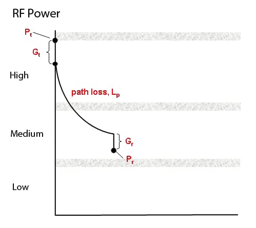
Other two-way TTE communications systems under development use a large transportable loop for transmitting and a ferrite rod antenna for receiving. The underground TTE antenna system could be carried into the working section each day by the miner or cached nearby. It would be prudent to check the TTE communications link regularly, in which case, the TTE should always remain deployed. Regardless of the approach, the TTE communications link appears to be highly survivable and therefore is likely to play a significant role as an emergency secondary or alternate communications path.
TTE communications system components should also be sufficiently rugged to withstand rough handling that may result during an emergency. As stated previously, underground components may be worn by personnel, contained in a suitcase-style enclosure, or integrated into the design of a refuge chamber. During escape, should a loop antenna need to be deployed, the wire gauge should be of sufficient size to withstand bending and be jacketed to resist abrasion. Portable transceivers must be resistant to the mechanical shocks anticipated during escape. Underground system components must be protected in storage from moisture and dust. Refuge chamber components should be sufficiently rugged to withstand the repeated chamber movement as the working section advances and retreats. The surface antenna must exhibit similar robust qualities of mechanical strength. Permanent surface installations should be resistant to weather and rodents.
As stated previously, low data rates and electrical noise underground would preclude using a TTE system for routine communications. However, future enhancements may allow TTE systems to bridge to medium frequency, node-based, or leaky feeder systems. Under those circumstances, the TTE system may be an alternate communications path out of the mine. With multiple transceivers underground, the TTE system may have applications for point-to-point underground communications and overlap with existing medium frequency, node-based, or leaky feeder systems.
2.5.6 Maintenance and Inspection
Underground caches can store multiple TTE portable units that miners can use during an escape. Routine inspections of these systems underground should detect system component failures. The present TTE systems are relatively complex and may require replacement of modules or entire units underground. Periodic checks of the batteries contained in both the portable and stationary TTE units are necessary. Regular functional communications tests are necessary between the portable and stationary units underground. Each time the refuge chamber moves, tests should reconfirm TTE communications with the surface. A troubleshooting manual in the nearest refuge chamber should have a checklist in the event that the TTE units do not operate during routine inspections.
2.5.7 Performance and Limitations
The feasibility of two-way TTE communications in underground mines has been demonstrated in several NIOSH-sponsored research contracts. These projects involved development of TTE prototype units which were evaluated at commercial mines. The systems used varied approaches to establish communications through the earth. Most systems featured magnetic field sensing, with one design based upon electric field propagation. Both digital and analog signal processing techniques were employed. Loop or line antennas were used for transmission. Noise filters or noise cancellation techniques were found to be necessary for signal reception. Underground-to-surface as well as underground point-to-point communications for voice and text were demonstrated at ranges exceeding 300 m (1,000 ft). The range generally increased with increasing transmit power levels. Prototype systems were often evaluated at power levels exceeding MSHA permissibility limits on the underground transmitter and will require further field evaluations to determine their range when operating at permissible power levels.
Through these research contracts, NIOSH provided companies an opportunity to demonstrate and develop technology solutions that they believe can help solve underground mine communications problems. There was considerable research conducted by the U.S. Bureau of Mines (USBM) in the early 1970s through the mid 1980s that documented the challenges and potential solutions to TTE communications. Based on their initial understanding of these challenges, most companies were initially very confident that they could readily achieve depths in excess of 300 m (1,000 ft) for voice and up to 600 m (2,000 ft) for text. In all cases, the manufacturers found the challenges to be much more difficult than they had expected. There are several possible explanations. First, the digital signal processing and noise cancellation techniques used for radio, radar, and sonar applications were not designed to be effective on the type of signals and noise experienced at these ultralow frequencies. Second, mining equipment typically operated at lower utilization voltages and horsepower in the 1970s and 1980s than at present (2011). Today’s equipment would be expected to generate a different electromagnetic noise profile. Lastly, as a result of continued development, the noise levels due to aboveground transmission lines and other manmade sources most likely have increased substantially in the last 30 to 40 years. Before this technology can be fully used by the mining industry, there are questions that remain to be answered. These questions relate to communications format, time delays, portability, deployment, noise characterization, interaction with other systems, and permissibility, which are briefly detailed below.
One question revolves around the choice of TTE communications format—specifically, text versus voice. From a technological standpoint, the signal range for text can be greater than for voice. Text can be transmitted at lower bit rates and lower frequencies, with preprogrammed canned messages having the greatest potential range. Text also has the advantage of being a familiar and well-accepted communications format for a workforce becoming more comfortable with computers. There are concerns over the ability to text under stressful, adverse, emergency conditions especially when smoke hinders visibility. Those same conditions, however, may also hinder voice communications when self-contained breathing apparatus are in use. The solution may lie in software which can convert voice input into text, and text into synthesized voice.
Another question focuses on what is an acceptable time delay for a message. Real-time communications without functional delays, as with conventional telephones, is a goal which may not be practically achievable or necessary. It is conceivable that a message can be transmitted and received, and a response made over several minutes without adversely affecting rescue or escape. As with message format, message delay times and range are impacted by bit rate.
Further questions revolve around the TTE hardware and its deployment. It could be stationary while in use, or it may need to be transportable. It may be used while workers are awaiting rescue or during their escape. Some systems may feature components in heavy explosion-proof enclosures, which could only be moved by equipment. Underground antennas could be predeployed by integration into the design of refuge chambers or be carried and deployed as needed by an escaping miner who might also have donned a self-contained self-rescuer (SCSR). On the surface, antennas may be permanently deployed directly above dedicated, hardened transceivers installed underground, or may be installed following an emergency on the surface above a rescue chamber.
Finally, it is known that the geology of the earth transmission path poses further challenges for the designer and users of TTE communications systems. The electrical conductance of the overburden has a great impact on the efficiency of transmission and can vary by orders of magnitude from mine to mine. For example, lower values of transmission path conductivity have reduced loss. Signal transmission with minimal loss is most easily achieved through materials with relatively low conductivity, such as air, granite, or sandstone. Higher conductivity materials such as salt or coal can impede transmission. The conductance of formation salt water (~5 S/m or ~0.2 ohms/m) is as much as 20 times that of coal—this may be of importance in certain areas of the U.S. where salt deposits exist in the overburden. It is unknown how certain geological features and anomalies such as mined-out seams and aquifers may affect transmission through the earth. Signal reflections at strata interfaces (for example, air-rock, water-rock, or coal-shale) will also likely reduce the effective coverage range. Maximum TTE system ranges can be simplistically extrapolated assuming a homogeneous overburden with uniform conductivity. For a point-to-point underground transmission, multiple entries, solid coal blocks, roof mesh, and/or gob could significantly alter the range.
Batteries will be required for emergencies when the power is off. A battery meter should indicate if batteries are within the proper operating voltage range. Underground components need to include an MSHA-approved intrinsically safe design.
For reception, the units may feature two or three ferrite-core antennas in an orthogonal arrangement. The ferrite cores enhance the magnetic field strength while permitting a compact design. Multiple, orthogonally arranged antennas ensure that reception is independent of the antenna orientation. Software can add the component signals from each antenna to obtain a resultant vector signal.
2.6 Communications Technology Comparisons
Currently there are four types of commercially available systems for underground coal mine wireless (or partially wireless) communications systems: node-based, leaky feeder, MF, and TTE. Although the hardware and software will differ from different vendors, there are some general capabilities and limitations that are inherent in these communications technologies. The comparison matrix in Table 2-3 compares the four technologies for a variety of attributes. Discussion of some of the table entries is given below.
It is important to note that MF systems and especially TTE systems are still under development and may have limited commercial availability at this time (as of Fall 2011). MF systems can use whatever continuous conductors already exist in the mine entries and hence are less reliant on special cables or equipment than more conventional techniques, although they are not totally immune to disruption. TTE systems are particularly useful because they do not need fixed structures underground which could be damaged. The inherent bandwidth limitations of both MF and TTE technologies restrict their use to either secondary or emergency-only situations (TTE in particular) or as an adjunct to more conventional technologies such as leaky feeder and node-based UHF systems. Leaky feeder and node-based technologies are the most commonly installed wireless systems to date. Leaky feeder technology has the longest successful history of usage in coal mines and tunnels, having been used since the early 1980s.
| Category | Feature | Leaky Feeder1 | UHF Node Based | Medium Frequency2 | Through-the-Earth |
|---|---|---|---|---|---|
| Coverage and Range | Coverage range - access link | < 50 m (150 ft) < 120 m (400 ft) |
< 300 m (1,000 ft)3 |
< 3.2 km (2 miles) |
< 600 m (2,000 ft) of cover |
| Coverage and Range | Expandability (adding components) | Moderate | Easy/Moderate4 | N/A5 | N/A |
| Installation | Design | Low | High | High | Moderate |
| Installation | Labor intensity | Moderate | Low | Low | Low |
| Installation | Infrastructure recovery | Difficult | Moderate | Easy | Easy |
| Functionality | High speed data | Yes6 | Yes | No | No |
| Functionality | Paging | Yes | Yes | No7 | Yes8 |
| Functionality | Peer to peer | Yes9 | Yes6 | Yes | N/A |
| Functionality | Text - low speed data | Yes | Yes | Yes | Yes |
| Functionality | Voice | Yes | Yes | Yes | Yes10 |
| Functionality | Troubleshooting via centralized test diagnostics11 | Moderate | High | Low | Low |
| Functionality | Interoperability12 | Open | Open, Proprietary | Proprietary | Proprietary |
| Survivability | Battery load - fixed infrastructure13 | High/Moderate | High | High/Low | Very High/Low |
| Survivability | Battery life - mobile | > 24 hours | > 24 hours | N/A5 | N/A5 |
| Survivability | Number of battery locations | Low | High | Low | Low |
| Survivability | Fault tolerant - hardware | Moderate | High14 | Low | Low |
| Survivability | System survivability15,16 | Moderate | Moderate | High | High |
- When two values are shown, they represent VHF/UHF systems respectively.
- Data for analog systems only.
- Varies with frequency and entry dimensions if nodes are line-of-sight (LOS). Mine stoppings and other obstacles will decrease range.
- May require a system redesign to expand.
- N/A - Not Applicable or Not Available.
- Vendor specific.
- Current technology.
- Currently available system has paging + text for downlink only.
- If hand-helds allow F1/F2 switching.
- Depth limited, system under development.
- Describes system requirement for effective troubleshooting.
- Does system use standard vs. proprietary interface protocols.
- Values for Transmit/Standby modes.
- Depends on installation details.
- System resistance to major disruptive events (fire, explosion, roof collapse, inundation) when properly implemented.
- Based on the number of components needed and/or complexity of setup.
- Advanced Tutorial on Wireless Communication and Electronic Tracking: Introduction
- Basic Tutorial on Wireless Communication and Electronic Tracking: Technology Overview
- Communication Systems Research At Bruceton Safety Research Mine
- Develop a Means to Model Network Performance Using Network Simulation Tools
- Propagation of EM Signals in Underground Mines
- Through-The-Earth Wireless Real-Time Two-Way Voice Communications
- Transmit Antennas for Portable VLF to MF Wireless Mine Communications
- Ultra-Low Frequency Through-the-Earth Communication Technology
- Underground Mine Communications
- Wireless Through-The-Earth Modeling and Support