
Engineering Controls Database
Control of Airborne Refractory Ceramic Fibers Using Local Exhaust Ventilation
| The friction between the wheel of the disc sander/ belt of the belt sander and the ceramic workpiece results in the release of particles and fibers. Those particles are ejected at high speeds along a path tangential to the rotation of the wheel. The respirable particles, if not captured, can be carried into the breathing zone of the worker resulting in exposure to the refractory ceramic fibers and dust particles. | |
| There are an estimated 30,000 workers who may be exposed to refractory ceramic fibers (RCFs) during the manufacture or use of products made from this material. A study of air samples collected in the manufacturing workplace indicated that some fiber dimensions were within the respirable size range. Results of inhalation tests with animals have shown that RCFs cause fibrosis and lung and pleural cancer when administered at very high doses (the “maximum tolerated dose” for 6 hours/ day, 5 days/week for 24 months). Worker exposure to RCFs can also increase eye irritation, stuffy nose, and dry cough. NIOSH concludes that RCFs are a potential occupational carcinogen. | |
|
Local exhaust ventilation is designed to capture the contaminant near the point of release. The effectiveness of a local exhaust ventilation system is highly dependent on the proximity of the exhaust hood to the point of emission. Contaminant capture efficiency decreases rapidly with distance. Therefore, the primary focus for effective control of airborne particles and fibers is collection at the point of generation. The disc sander is mounted on a pedestal to allow the worker to conveniently stand while sanding parts. The sander, which operates at a speed of 1150 revolutions per minute, uses a 20 inch diameter wheel with 50 grit zirconium abrasive. The disc sander was outfitted with a local exhaust ventilation (LEV) system. An aluminum shroud encloses the entire disc with the exception of one small opening to allow access for parts to be sanded. Since the shroud opening is adjustable, parts of various dimensions can be sanded easily. A ventilation duct take-off is located on the lower rear of the sander and uses a 6-inch flexible duct that connects into a rigid aluminum main exhaust duct that also provides exhaust outlets for other workstations within the plant. A Pitot tube traverse was performed in the 6-inch rigid duct to determine the exhaust airflow rate for the shroud ventilation system. The velocity in the duct was 5400 feet per minute, which yielded an overall exhaust flow rate of 1060 cubic feet per minute. The system evaluated in this study consisted of two hoods (or pick-up points). The first hood is a moveable “elephant trunk” type, which should be positioned as close to the workpiece as possible during sanding. A 6.25 inch diameter opening with a bell mouth inlet was used to minimize hood entry pressure loss. This hood was placed within 3-6 inches from the workpiece during each trial. A second hood is located just under the work surface to collect any material that is entrained in the airflow generated by the motion of the belt or disc. This pick up point not only aids in removing airborne particles but also assists in keeping the work area clean. 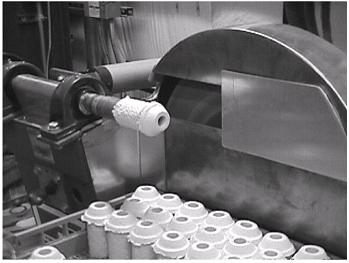 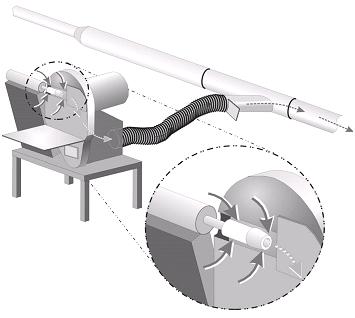 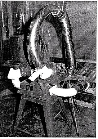 |
|
| 246-11-A; | |
| 32711 | |
|
belt sanding ceramic fiber parts ceramics disc sanding drilling grinding refractory refractory ceramic manufacturing refractory ceramics sanding sawing |
|
| A local exhaust ventilation system consisting of two hoods resulted in reductions in personal airborne fiber concentrations of greater than 99% for both disc and belt sanding. |