HIGHWAY WORK ZONE SAFETY
Construction Equipment Visibility
NIOSH Manual Method
In 2001 NIOSH began evaluating promising strategies to prevent workers from being struck by construction vehicles and equipment operating in roadway work zones. The evaluation methods required the use of equipment blind area diagrams, which were developed using two approaches. First, NIOSH contracted with Caterpillar, Inc. to use standard test methods (physical measurements and computer simulations) for creating blind area diagrams. Second, NIOSH staff developed a manual method for creating blind area diagrams in a relatively short period of time. Although none of the blind area diagrams shown in this web site were created using the NIOSH manual method, it is explained here as a low-tech alternative. The NIOSH manual procedure is more subjective than the ISO methods used by Caterpillar, Inc; however, the NIOSH procedure does not require specialized apparatus or software (e.g., measuring seat index point, mounting light filaments, computer design drawings) and it does not require a particular location (i.e., large, enclosed warehouse where light shadows can be projected on a grid). The NIOSH manual method can be used by construction companies, labor unions, and training organizations to better understand the blind areas around their own equipment.
For the NIOSH manual method, blind areas are defined as those areas where the equipment operator, who is seated in the equipment cab, cannot see an object by direct line of sight or in mirrors. Three different objects are of interest: 1) the ground itself, 2) a road construction barrel, and 3) a worker. This procedure results in three blind area plots that define the visibility around these three objects of interest, represented respectively by the following heights: the ground, 900 mm above the ground, and 1500 mm above the ground.
Test Site Preparation
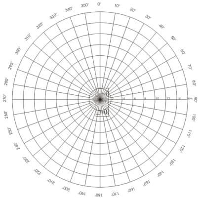
A flat area at least 24 m on each side, such as a gravel or asphalt parking lot, is required for the layout of the test grid. The area should be cleared of any large debris. Using a surveyor’s transit, mark a polar grid on the test site using stakes, spray paint, paint stick markers, or any other marker that will be immobile for the duration of the test. The polar grid consists of 16 m long lines radiating from the center of the grid at 10 degree intervals and a series of concentric circles, centered on the grid at 2 meter intervals (see Figure A-1). The outer circle has a 16 m radius. To measure blind areas for larger equipment, additional circles with larger radii may be needed.
Figure A-1. Polar plot with scaled outline of a Ford F-800 dump truck and 2 meter concentric circle marks.
Blind Area Mapping Crew
The blind area mapping crew consists of a driver, an observer, a recorder, and two point measurers. An additional recorder helping the two point measurers increases mapping efficiency.
Equipment Preparation
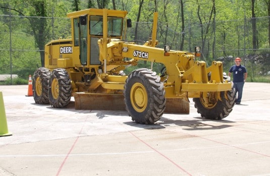
To record the blind areas around the equipment, an average height driver (1715 mm) provides feedback regarding what areas can and cannot be seen. The driver adjusts the mirrors and seat height of the equipment in accordance with the equipment operator’s manual. The equipment is moved over the test grid so that the driver’s seat is directly over the center of the grid and the 0 degree line is straight in front of the driver and parallel with the long axis of the equipment (see Figures A-1, A-2). The engine is turned off, the parking brake set, and the tires are blocked. Attachments (e.g. buckets, blades) are set as they would be when moving the equipment and are blocked in place.
Figure A-2. Motor grader placed on polar grid.
Marking Blind Areas
During the tests, the driver remains seated in the cab in a normal driving posture. It is important that the driver’s body remain as still as possible in the seat. The driver may turn his/her head and torso, but not beyond what would be considered a normal driving posture. The driver may look out, but not lean out, any windows. The driver may use any mirrors that are standard for that piece of equipment. If after-market mirrors have been added to the equipment, the areas that are visible using these mirrors can be recorded, but should be noted as such.
Ground Visibility:
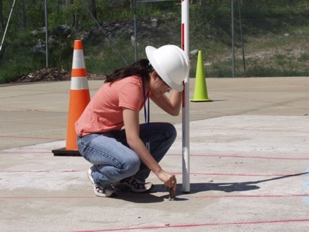
To determine where the ground cannot be seen by the driver, an observer walks along the radial grid lines and marks those areas where the driver indicates that the ground is not visible. The observer starts at the 0 degree line as close to the equipment as possible. While the observer walks along the line and away from the equipment, the driver signals when the bottom of the observer’s shoes become visible. The observer then uses a level rod or other pointing device to find the exact location where the driver can see the ground. A mark is placed on the ground at each point that a transition occurs between visible and not visible. The mark can be made with spray paint, chalk or a removable marker such as a small wood block (see Figure A-3). The observer then continues to mark points along this line where necessary. When the 12 m radius is reached, the recorder moves back to the equipment and walks the next degree line. As the observer marks points on the ground, points are recorded on a polar plot, such as shown on Figure A-1, by a recorder (a scaled outline of the actual equipment, superimposed on the graph, is helpful, but optional).
Figure A-3. Observer marking points on polar grid.
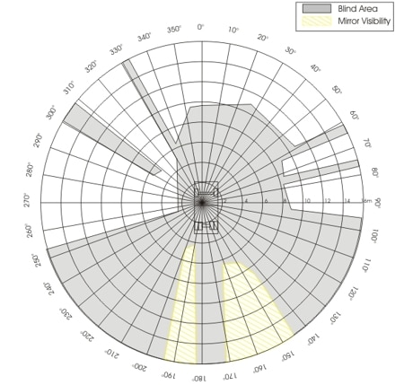
As the observer walks each degree line and progresses around the truck, it may be necessary to mark additional points while estimating intermediate degree lines or radius marks. This helps to define the exact nature of the blind area. Also, some blind areas tend to fan out to infinity. In this case, the process can be shortened by immediately walking to the outermost circle and marking the transition points on this circle. For example, in Figure A-4, the right edge of the windshield creates a blind area that extends out toward 60 degrees. As the observer walked the 60 degree line, a marker was placed at 10.5 m indicating the first point at which the driver could see the ground. Because this area was recognized as a blind spot that extended out to infinity, the observer immediately went out to the outermost circle to determine where this blind area began (61 degrees) and ended (65 degrees).
Figure A-4. Blind area diagram for Ford F-800 dump truck showing where the operator cannot see a point at ground level (dark grey) and where the operator can see a point at ground level in a side view mirror (yellow hash).
The initial test is complete after all degree lines have been tested; however, the blind areas need to be better defined. To do this, the observer tests intermediate points between markers where necessary. Interpolation between markers results in a more accurate outline.
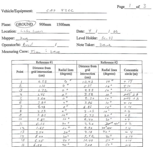
After verifying and refining the blind area marks, the two point measurers record the polar coordinates of the marks made on the ground by the observer. Each mark lies within or on a sector of the grid, defined by two circles and two radial lines (the circles are 2 m apart, the lines 10 degrees apart). Of the sector’s four corners, the two closest to the center of the grid are used for measuring the polar coordinates for each blind area mark. When measuring cannot be achieved using the inner two corner points (e.g. machinery obstructs the measuring process), the outer grid points can be used. Coordinates are recorded on data sheets using polar grid points as references (see Figure A-5).
Figure A-5. Sample data sheet used to record the polar coordinates of points that define blind areas around construction equipment.
Construction Barrel and Worker Visibility:
The method for determining where a construction barrel and worker cannot be seen is similar to the above procedure. Instead of using the bottom of the observer’s shoes and the bottom of a level rod, an obvious mark is placed on the level rod at 900 mm (barrel) or 1500 mm (person). The observer holds the pole in an upright position and places it on the test area grid points. The driver indicates to the observer whether or not the mark can be seen. A marker is then placed at the bottom of the level rod to mark the spot on the ground where each visibility transition occurred. The marks are then recorded as before.

