
Farmer Drowned While Removing Stop Logs From Water Level Control Structure
Michigan Case Report: 08MI135
Summary
|
|
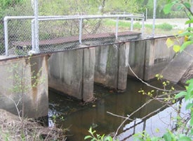
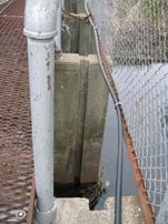
Figure 1. Upstream side of water level control structure looking east.
|
In June 2008, a 76-year-old male farmer, who was a member of a volunteer cooperative drowned, as he was removing wood stop logs from the drain’s water level control structure to relieve a high upstream water level (Figure 1). The structure had three sections six feet wide. Each section had at its base, one 12-inch wide wooden stop log that was turned on its edge. Stacked on top of the 12-inch stop log were four 8-inch wide stop logs, also turned on their edge. The five stop logs were held in place by a channel in the concrete piers. At the time of the incident, each section had its full complement of stop logs. A large amount of precipitation and the area’s soil composition caused water to run off to the field’s drainage ditches and into the county drain resulting in high upstream water levels in the drain and ditches and field flooding. The decedent arrived at the water level control structure, parked his vehicle, removed his work boots, and donned chest waders. He stood downstream in the southernmost section and used a crowbar to loosen the top stop log. He lifted the top stop log up and out of the channel. After removing the stop log from the channel, he either slipped and lost his balance or was knocked over by the force of the water rushing over the remaining stop logs. A nearby landowner saw the decedent’s unattended vehicle, and when he couldn’t find him, called for emergency response. The police arrived, and called for the dive team. The decedent, who was not wearing a life jacket, was found 40 feet downstream, caught by low hanging tree branches.
Recommendations:
- The drain commissioner should ensure that a standard operating procedure to add/remove stop logs for each of the county’s water control structures is developed and implemented. This procedure should prohibit individuals from entering the drain to remove the stop logs.
- The drain commissioner, when a possibility of drowning exists, should require volunteers to wear an approved life jacket/buoyant work vest and have a ring buoy available.
- The drain commissioner should have an annual safety meeting in early Spring with the volunteer cooperative members to review safety and operation procedures.
- The drain commissioner should review all water level control structures walkway handrails to ensure compliance with MIOSHA General Industry Safety Standard, Part 2 – Floor and Wall Openings, Stairways, and Skylights.
Introduction
In June 2008, a 76-year-old male farmer, who was a member of a volunteer cooperative responsible for county drain maintenance, drowned as he was attempting to remove a wood stop log from a water level control structure to relieve a high upstream water level in a drain. An MSU extension director from a nearby county notified MIFACE personnel of this fatal injury. On May 7, 2009, MIFACE personnel spoke with the county drain commissioner, and on May 15, 2009, MIFACE visited the site with the county’s MSU extension director. MIFACE also spoke with a cooperative member who had worked with the decedent in the past regulating water levels in the drain and who had noticed the decedent’s truck unattended. Pictures used in Figures 2, 3, and 7 are courtesy of the county extension director. Pictures used in Figures 1, 4, 5, and 6 were taken at the time of the site visit by the MIFACE researcher.
The decedent worked a 214-acre farm. His farm was located approximately 4.5 miles from the water control structure. The drain ran through his property.
The county drain commissioner serves as an agent for drainage districts in the county. The county drainage district is considered the “owner” of the drain. The drain commissioner, based on input from local agricultural growers, formed volunteer cooperatives whose agricultural operations were drained by a county drain. The cooperatives were formed because of different drain and groundwater needs for the crops grown in the drain’s drainage area. The cooperatives were responsible for monitoring and regulating the water levels in the drain. Cooperative members took turns removing/adding stop logs to the water level control structure as dictated by water level or agricultural need. The decedent was a founding member of a three-grower cooperative that included growers of blueberries, row crops, and ornamental plants. The drain provided drainage for approximately 3,520 acres.
The drain commissioner noted to the MIFACE researcher that discussion of a policy manual was held between the drain commissioner and the cooperative volunteers. The drain commissioner intended the volunteers to affix their signature to indicate that they would abide by the manual’s policies. The drain commissioner said that the cooperative members declined to sign the document because they were volunteers and due to weather conditions, they regulate water levels in the drains at their discretion. MIFACE did not see the proposed policy manual to determine if the safety and health provisions were adequate.
Investigation
Weather history for the area included approximately 107 inches of snow from November 2007 to March 2008, 3.6 inches of rain in April 2008, 2.96 inches of rain in May 2008, and 4.51 inches of rain in June 2008, of which 4.03 inches occurred the day prior to the fatality. The soil consisted of granular topsoil with a hardpan layer under it.
|
|
|
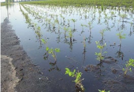
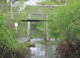
Figure 2. Example of water levels in field drainage ditch and field upstream of drain.
|
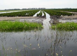
Figure 3. Example of water in fields upstream of drain and height of water in drain.
|
Because of the soil characteristics and the amount of precipitation, the soil became saturated and caused water run off to field drainage ditches and the county drain. The amount of water overwhelmed both field drainage ditches and the county drain, causing field flooding upstream of the water level control structure (Figures 2 and 3). On the day of the incident, the decedent did not contact other cooperative members to assist him in removing the stop logs. The decedent drove to the water level control structure site. After parking his truck, he removed his boots and donned chest waders. He did not wear a life preserver.
 |
|
|
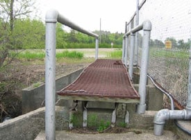
Figure 4. Water level control structure’s wood and expanded metal walkway, handrails, and fence, looking south.
|
Figure 5. Channels holding stop logs.
|
 |
|
Figure 6. Downstream side of the water level control structure, looking west, showing decedent’s location under the structure.
|
The water level control structure was constructed of a 31-inch wide expanded metal walkway that was attached to a deteriorating wood platform. The walkway/wood platform was secured to two abutment concrete walls and two piers spaced six feet apart. Two metal handrails were located on each long side of the walkway. The 4-inch diameter east handrail was secured only to the north and south concrete abutment. The 3-inch diameter west handrail (upstream side of the structure) was secured to the north and south concrete abutments and had support pipes to the two middle concrete piers (Figures 1, 4 and 6 ). The top of the rails were 31 inches from the walking surface of the walkway. No midrails were present. A fence was approximately 18 inches from the west handrail. All of the concrete support structures had a channel into which the stop logs were inserted to regulate water levels in the drain (Figure 5). Five umber stop logs, each turned on their edge, were placed within the channels of each of the three sections of the structure. Each section had at its base one 12-inch wide stop log. Placed on top of the 12-inch wide stop log were four 8-inch wide stop logs. At the time of the incident, all three sections of the structure contained the full complement of stop logs. The stop log height from the base of the bottom stop log to top of the topmost stop log was 44 inches.
|
|
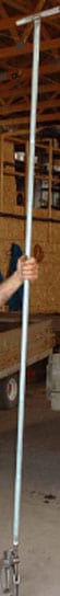
Figure 7. Tool developed to add/remove stop logs.
|
The cooperative member stated that he and the decedent, both individually and working together, had removed/added stop logs to the water level control structure. The cooperative member indicated that he saw the decedent’s truck near the structure at 10:45 a.m. Approximately two hours later he noticed the truck had not been moved and decided to investigate the situation. He found the truck window open, the truck keys in the ignition, and the decedent’s work boots on the ground near the truck. He looked around for the decedent. Not finding him, he called for emergency response. The local police arrived, and then a K9 unit. The dive team was then dispatched. The decedent was found a short time after the arrival of the dive team.
The cooperative member described the stop logs removal work practices of the decedent when they had jointly removed the stop logs. Although this was a non-witnessed event, it is probable that the decedent followed the practices described by the cooperative member. The decedent, who was approximately 5 feet 9 inches tall, entered the drain on the downstream side of the structure. The sill downstream side was approximately six to eight inches lower than the upstream side, thus making the base of the topmost stop log approximately 31 to 38 inches high. He used a crowbar to pry the topmost stop log up and out of the channel on the southernmost section of the structure.
As he was lifting the stop log, water flowing under it may have entered into his chest waders. As he removed the stop log from the channel, he may have slipped on the concrete sill of the structure and/or knocked over by the force of the water rushing over the top of the remaining stop logs. He was found approximately 40 feet downstream, caught by low hanging tree branches. He was partially submerged in the water and holding the stop log he had removed. His waders were full of water.
This water level control structure was the only structure in the county that did not have eye bolts screwed into the stop logs to assist the volunteers when adding or removing the stop logs. Volunteers use tools to be inserted into the eyebolts so stop logs could be handled on the walkway instead of standing at the base of the water line.
Remediation
A local farmer developed a tool to permit the addition and removal of the stop logs while standing on the structure’s walkway. The user turns the handle, causing the tool shaft to twist, which opens and closes the 10-inch clamp at its base.
Cause of Death
The cause of death as listed on the death certificate was fresh water drowning. Toxicology was negative for alcohol and illegal drugs.
Recommendations/Discussion
The drain commissioner should ensure that a standard operating procedure to add/remove stop logs for each of the county’s water control structures is developed and implemented. This procedure should prohibit individuals from entering the drain to remove the stop logs.
The decedent, according to the cooperative member, normally entered the drain to remove the stop logs. As a founding member of the cooperative, his work practice had been in place for many years. The cooperative member who spoke with the MIFACE researcher and had worked with the decedent in the past, had mentioned to the decedent that he would not, and neither should the decedent, enter the drain to add or lift a stop log out of the channel The cooperative member’s practice was to enter the drain, loosen the stop log and lift it slightly with a crowbar, place a chain under the stop log, and then exit the drain, stand on the walkway and use the chains to lift the stop log from the concrete structure.
The drain commissioner indicated he was not aware of the work practices taking place at the incident drain. He noted that stop logs on the other water level control structures had eyebolts into which tools could be used to permit the individual adding and removing the stop logs to stay on the structure and “out of harm’s way.”
As a rule, an organization can require volunteers to adhere to the organization’s policies and procedures. The drain commissioner had held a discussion with volunteer cooperative members about a policy manual. Because each water level control structure has a unique configuration and hazards, a standard operating procedure should be developed to add and remove stop logs from the structure.
The drain commissioner should require volunteers to follow the standard operating procedure when performing work at the water level control structure. The drain commissioner could: a) develop the procedures and train cooperative members about the procedures, b) bring the cooperative members together, and as a group, develop and implement standard operating procedures to ensure the safety of the volunteers, and/or c) direct each cooperative “assigned” to a drain and its water level control structure to develop these procedures, because they are familiar with the structure’s characteristics. The drain commissioner should review each procedure to ensure that it adequately protects cooperative members, and then ensure the procedure is implemented.
This procedure should prohibit individuals from entering the drain to remove stop logs. The standard operating procedure should also contain a provision that ensures anytime stop logs are added or removed from a structure that two people are present. Additionally, the procedure should require the wearing of a life jacket/buoyant vest when a possibility of drowning exists.
The drain commissioner, when a possibility of drowning exists, should require volunteers to wear an approved life jacket/buoyant work vest and have a ring buoy available.
Although not technically a construction activity, it is possible for a volunteer worker to drown if he/she fell from a water level control structure while adding/removing stop logs, or if work, such as clearing debris in a drain which may have water in it, is undertaken. MIOSHA Construction Safety Standard, Part 6, Personal Protective Equipment can provide guidance to minimize that a drowning incident could occur. The drain commissioner should require the wearing of a life jacket/buoyant vest. The work practices identified in the standard operating procedures developed for each structure and for any drain work performed should comply with Part 6, Rule 636, Working over or near water:
- Where a possibility of drowning exists, an employee working over or adjacent to water shall wear a life jacket or buoyant work vest.
- The life jacket or buoyant vest shall bear a label, “U. S. Coast Guard approved.”
- The jacket shall be of a type to roll the wearer face up, if unconscious.
- Before each use, the life jacket or buoyant vest shall be inspected for defects, which might alter its strength or buoyancy. Defective units shall not be used.
- A ring buoy with not less than 90 feet of safety line shall be provided and shall be readily available for rescue operations. The distance between the buoys shall not be more than 200 feet.
Rule 636 also requires at least one lifesaving boat equipped with a method of propulsion that is effective for the water conditions shall be available at the location where an employee works over or adjacent to water and the possibility of drowning exists. Each drain and water level control structure should be evaluated to determine the practicality of this requirement. The requirement may not be practical as many drains are narrow and the water may be too shallow or flowing too swiftly to operate a water craft.
The drain commissioner should have an annual safety meeting in early Spring with the volunteer cooperative members to review safety and operation procedures.
An early Spring safety meeting provides an opportunity for the drain commissioner and cooperative members to engage in an interactive discussion to share information about past problems (and how they may have been resolved), equipment issues, safe work practices, or any other health and safety problem that could contribute to a work-related accident which could exist during the season as they manage the water levels in the drain. Cooperative members benefit from getting together to learn from each other, gaining the knowledge they need to recognize hazards, solve problems and work safely. The drain commissioner benefits as he/she hears about the issues surrounding drain management and emphasizes to volunteers the drain commissioner’s safety commitment.
The drain commissioner should review all area water level control structure walkway handrails to ensure compliance with MIOSHA Safety Standard, Part 2 – Floor and Wall Openings, Stairways and Skylights.
It appears that guardrails (i.e. handrails) were used to protect the cooperative members (and the public) as they were walking or working on the water level control structure.
MIOSHA General Industry Safety Standard, Part 2, specifies the standard barrier requirements to prevent an individual from falling from a walking or working surface. Part 2, Rule 231(1) describes a standard barrier as consisting of a vertical barrier that extends not less than 42 inches above walking or working surface. NOTE: a standard barrier that was installed before August 28, 1973 to a height of not less than 36 inches is exempt from the 42-inch requirement, except that all future alterations must comply with the 42-inch requirement. Additionally, Part 2, Rule 231(6) identifies the requirements of a fail-type system which include a top rail and an intermediate rail or rails, which is required to be located halfway between the top rail and the walking or working surface.
Although the cooperative members were volunteers and not employed by the drain commissioner, the 31-inch high guardrails installed at the incident structure did not meet either the exemption of 36 inches if installed prior to August 28, 1973 nor the MIOSHA standard (42 inches) for height. The barrier also did not have the required intermediate rail.
MIFACE recommends that the drain commissioner conduct a survey of all water level control structures in the county to assess compliance with MIOSHA standards for guardrails and make necessary modifications.
Acknowledgement
MIFACE would like to acknowledge the assistance of Jeffrey E. Friedle, P.E., an agricultural engineer with 30 years of professional experience. Mr. Friedle performs drain and dam engineering/inspections and designs for county government and private development throughout Michigan.
References
MIOSHA standards cited in this report may be found at and downloaded from the MIOSHA, Michigan Department of Energy, Labor & Economic Growthexternal icon (DELEG) website at: www.michigan.gov/mioshastandards. MIOSHA standards are available for a fee by writing to: Michigan Department of Energy, Labor & Economic Growth, MIOSHA Standards Section, P.O. Box 30643, Lansing, Michigan 48909-8143 or calling (517) 322-1845.
- MIOSHA Construction Safety Standard, Part 6, Personal Protective Equipment.
- MIOSHA General Industry Standard, Part 2, Floor and Wall Openings, Stairways, and Skylights.
- National Climate Data Center, NOAA Satellite and Information Serviceexternal icon. Internet Address: http://www.ncdc.noaa.gov/ (Link updated 4/1/2013)
Key Words: Drowning, Drainage ditch, Water level control structure, Drain commissioner, Agriculture
Michigan FACE Program
MIFACE (Michigan Fatality Assessment and Control Evaluation), Michigan State University (MSU) Occupational & Environmental Medicineexternal icon, MIFACE (Michigan Fatality Assessment and Control Evaluation), Michigan State University (MSU) Occupational & Environmental Medicine, 117 West Fee Hall, East Lansing, Michigan 48824-1315; http://www.oem.msu.edu. This information is for educational purposes only. This MIFACE report becomes public property upon publication and may be printed verbatim with credit to MSU. Reprinting cannot be used to endorse or advertise a commercial product or company. All rights reserved. MSU is an affirmative-action, equal opportunity institution. 10/22/09
Link updated 05/25/2010
MIFACE Investigation Report #08MI135 Evaluationpdf iconexternal icon (see page 10 of report)
External link: http://www.oem.msu.edu/MiFace/08MI135.pdf#page=10