
Engineering Controls Database
Guidelines for the Control and Monitoring of Methane Gas on Continuous Mining Operations – Moving Air to the Mining Face – Airflow between the Mouth of the Blowing Curtain and the Face
|
The introduction of conventional mining methods, which increased the rate of mining, was an important step in the mechanization of mining. The intermittent nature of the conventional mining process halted the extraction process for ore-loading and usually allowed time for methane gas to be dispersed. However, the introduction of continuous mining machines in the 1940s produced a constant flow of ore from the working face of the mine and resulted in an increase in methane levels. The number of face ignitions increased as more continuous mining machines were placed underground. Methane levels were found to be dangerously high. In some cases, methane concentrations measured 20 ft from the mining face exceeded the lower explosive limit (5% by volume) [USBM 1958]. The need for better face area ventilation was recognized to reduce the potential for explosions. |
|
|
Excessive levels of methane gas can affect the safety of the underground work force. Available methane control systems have been challenged in recent years by mining developments which include the use of continuous mining machines. Most mining accidents today generally involve only a few individuals. However, the infrequent occurrence of gas explosions puts the lives of the entire underground workforce at risk. In the past 10 years, explosions have led to 65 fatalities and 18 injuries with major explosions occurring at the Sago Mine in West Virginia in 2006 (12 fatalities and 1 injury), the Darby No. 1 Mine in Kentucky in 2006 (5 fatalities and 1 injury) and, most recently, at the Upper Big Branch Mine in West Virginia in 2010 (29 fatalities) [NIOSH 2011]. |
|
|
The U.S. Bureau of Mines (USBM) was formed in 1910 following a series of underground explosions that resulted in many fatalities and injuries [Kirk 1996]. The agency was responsible for conducting scientific research and disseminating information on the extraction, processing, use, and conservation of mineral resources. The USBM research program for mining health and safety was transferred to NIOSH in 1996. Since that time, NIOSH has established a ventilation test gallery where techniques for methane control and monitoring are evaluated under a variety of conditions that simulate airflow near the working face of a continuous mining section. Airflow patterns and methane concentrations are studied in a detailed manner that is not possible in a working underground mine. Moving Air to the Mining Face Effective face ventilation requires that a sufficient quantity of intake air be delivered to the mining face in order to dilute liberated methane to a safe level. Federal regulations include the following requirements: • Face ventilation control devices shall be used to provide ventilation to dilute, render harmless, and to carry away flammable, explosive, noxious, and harmful gases, dusts, smoke, and fumes [30 CFR 75.330]. • A minimum quantity of air (3,000 ft3/min) is required at each face area [30 CFR 75.325]. A mine operation must specify in its ventilation plan the minimum quantity of air required to maintain methane levels below 1% at their working faces. Early USBM research examined ways to deliver air to the end of the curtain or tubing with minimal losses. Recent NIOSH research has examined more effective ways to move air from the end of the curtain to the face. New monitoring instruments and sampling techniques made it possible to examine how operating conditions affect airflow inby the curtain or tubing. Airflow between the Mouth of the Blowing Curtain and the Face Past studies evaluated the movement of air between the end of the curtain or tubing by observing the movement of smoke generated with chemical tubes and making velocity measurements with vane anemometers or pitot tubes [USBM 1969]. Smoke patterns were more difficult to evaluate where the airflow was turbulent. Accurate velocity readings were more difficult to obtain near the face because flow direction was constantly changing. Better instrumentation was needed for monitoring flow direction and velocity near the mining face. One-, two-, and three-axis ultrasonic anemometers were obtained for making airflow measurements in the ventilation test gallery. The two- and three- axis instruments were used to measure flow speed and direction in the area between the face and the mouth of the curtain [Taylor et al. 2005]. The first tests were conducted in the test gallery where 16½- or 13-ft wide empty entries were simulated. Measurements were made with curtain setback distances of 15, 25, and 35 ft and intake flow quantities of either 6,000 or 10,000 ft3/min. Most of the airflow sampling locations were 4 ft from one another and 2 ft from the sides and face of the entry. Figure 1 shows the 36 sampling locations used for the 35-ft setback tests. Techniques for positioning the anemometers are described in (NIOSH) Publication No. 2010-141 (see below). 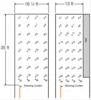 The individual measurements were used to draw the airflow profiles. Figure 2 shows airflow profiles for 10,000-ft3/min intake flow tests. Vectors indicate each sampling location and direction of airflow. Vector length is proportional to the air velocity in the direction of the flow. Similar profiles were obtained for 6,000-ft3/min intake flow tests, but the velocities were lower. • Decreasing curtain setback distance increased air velocities. • Entry width affected the flow patterns and velocities. For 25- and 35-ft setback distances o Flow patterns in the 13-ft wide entry resembled a figure “8” with flow moving right to left across the face. o Flow patterns in the 16½-ft wide entry resembled a “U” shape with air moving left to right across the face. o Air velocities were much higher in the 16½-ft wide entry. • For the 15-ft setback distance, airflow moved left to right across the face for both entry widths. 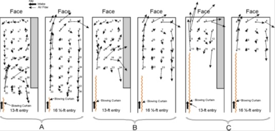 |
|
|
NIOSH [2010]. Information circular 9523. Guidelines for the control and monitoring of methane gas in continuous mining operations. Morgantown, WV: U.S. Department of Health and Human Services, Centers for Disease Control and Prevention, National Institute for Occupational Safety and Health, DHHS (NIOSH) Publication No. 2010-141. Kirk WS [1996]. The history of the Bureau of Mines. In: U.S. Bureau of Mines Minerals Yearbook, 1994. Washington, DC: U.S. Bureau of Mines. NIOSH [2011]. Ventilation and explosion prevention highlights. [http://www.cdc.gov/niosh/mining/highlights/programareahighlights16.html] Taylor CD, Timko RJ, Thimons ED, Mal T [2005]. Using ultrasonic anemometers to evaluate factors affecting face ventilation effectiveness. Presented at the SME Annual Meeting, Salt Lake City Utah, February 28–March 3, Preprint 05-80. USBM [1958]. Auxiliary ventilation of continuous miner places. By Stahl RW. Washington, DC: U.S. Bureau of Mines, Report of Investigations, No. 5414. USBM [1969]. Face ventilation in underground bituminous coal mines. By Luxner JV. Washington, DC: U.S. Bureau of Mines, Report of Investigations, No. 7223. |
|
|
coal mining continuous mining operations deep-cut mining miners |