
Engineering Controls Database
Best Practices for Dust Control in Coal Mining – Longwall Mining Operations –Shearer Dust
|
Respirable dust exposure has long been known to be a serious health threat to workers in many industries. In coal mining, overexposure to respirable coal mine dust can lead to coal workers’ pneumoconiosis (CWP). CWP is a lung disease that can be disabling and fatal in its most severe form. In addition, miners can be exposed to high levels of respirable silica dust, which can cause silicosis, another disabling and/or fatal lung disease. Exposure to coal mine dust may also increases a miner’s risk of developing chronic bronchitis, chronic obstructive pulmonary disease, and pathologic emphysema. Once contracted, there is no cure for CWP or silicosis. The goal, therefore, is to limit worker exposure to respirable dust to prevent development of these diseases. |
|
|
CWP contributed to the deaths of 10,406 U.S. miners during 1995–2004 [NIOSH 2008]. Pneumoconiosis continues to be a very serious health threat to underground coal mine workers. Longwall workers can be exposed to harmful respirable dust from multiple dust generation sources, including the intake entry, belt entry, stageloader/crusher, shearer, and shield advance. On most longwall faces, the cutting action of the shearer is the primary respirable dust source and accounted for over 50% of dust generated during mining in a previous study [Colinet et al. 1997]. Therefore, shearer generated dust should be the major focus of any longwall dust control effort, especially if a bidirectional cutting sequence is used. |
|
|
The following is a discussion of a number of technologies for controlling shearer-generated dust. Face ventilation. In coal mining, ventilation is the primary means to dilute liberated methane to safe levels. It is also the principal method of controlling respirable dust on the longwall face. Providing adequate amounts of air to dilute and carry airborne dust down the face and prevent it from migrating into the walkway has been and continues to be a goal for longwall operators. Previous studies [Mundell et al. 1979] have reported that face air velocities of 400–450 feet per minute (fpm) seem to be the minimum appropriate to control respirable dust. A German study [Breuer 1972] reported that the optimum velocity range may be increased to 700–900 feet per minute (fpm) when the moisture content of the dust particles is 5%–8%. An MSHA study [Tomb et al. 1992] reported that as face air quantities increased, even beyond 1,200 fpm, respirable dust levels along the face decreased. As air velocities increase, it is important to ensure that sufficient wetting of the coal is provided to minimize the potential of increased entrainment with the higher air velocities. The higher velocities provide greater air quantities for better dilution of intake dust, as well as dust generated during shield support movement. Higher velocities over the shearer help confine the dust to the face area and lower the potential for contaminating the walkway. Also, the higher velocities will improve the diffusion of dust from stagnant areas in the headgate and along the support line. In recent NIOSH surveys [Rider and Colinet 2007], the average velocity was 665 fpm, and two longwalls had velocities over 800 fpm. The average quantity of air along the face was 67,000 cubic feet per minute (cfm), an increase of about 65% compared to the mid-1990s longwall study [Colinet et al. 1997]. Drum-mounted water sprays. Drum-mounted water sprays apply water for dust suppression directly at the point of coal fracture and add moisture to the product to minimize dust liberation during coal transport. Although very effective at minimizing dust generation at the point of coal fracture, shearer drum water sprays can actually increase airborne respirable dust levels if operated at water pressures that are too high. Instead of suppressing dust generation, these sprays can force the dust out away from the cutting drum, allowing it to mix with the primary airflow, where it is then carried throughout the entire cross-sectional area of the longwall face [Jankowski and Colinet 2000]. Previous studies [Shirey et al. 1985] have shown that shearer drum water sprays are very effective at minimizing dust generated, but increasing shearer drum water spray pressure above 100 psi can increase the shearer operator’s dust exposure by as much as 25%. For most operations, the optimum operating drum spray pressure seems to be 80–100 pounds per square inch (psi). Full-cone sprays are the most effective type of spray pattern to use in shearer drums. These sprays increase wetting without inducing substantial air movement around the drum. Reducing nozzle pressures while increasing water quantity can be accomplished by installing spray nozzles with larger orifices that provide greater flow at reduced operating pressures. Cutting drum bit maintenance. Previous research has shown that bits with large carbide inserts and a smooth transition between the steel shank and the carbide reduce dust levels [Organiscak et al. 1996]. The prompt replacement of damaged, worn, or missing bits cannot be overemphasized. A dull bit rubs against the coal, which results in an ineffective use of the available cutting force and the inability to penetrate the coal at designed rates. This results in shallow cutting, which greatly increases dust generation. Not only do dull bits result in higher cutting forces and more dust, but there is also an increased likelihood for mechanical damage of bit holders and gear boxes and for frictional ignition of methane [Shirey et al. 1985]. Directional water spray systems. Water sprays can be very efficient air movers and, if applied properly, can be used to augment the primary airflow and reduce the amount of shearer-generated dust that migrates into the walkway near the shearer. Water sprays mounted on the shearer body act very much like small fans, moving air and entraining dust in the direction of their orientation [Jankowski and Colinet 2000]. Poorly designed shearer-mounted spray systems with nozzles directed upwind at the cutting drums actually force dust away from the face, where it mixes with clean intake air and is carried out into the walkway over the shearer operators. A directional spray system called the shearer-clearer [Jayaraman et al. 1985] takes advantage of the air-moving capabilities of water sprays and confines the dust-laden air against the face. It consists of several shearer-mounted sprays oriented downwind to augment the primary ventilation airflow. Also, it includes one or more passive barriers that split the airflow around the shearer into clean and contaminated air (Figure 1). The air split is initiated by a splitter arm that extends from the walkway side of the shearer body parallel to the headgate ranging arm. Conveyor belting hangs down from the splitter arm to the pan line to provide a physical barrier between the face conveyor and the walkway. In addition, a series of water sprays is mounted on top of the splitter arm to induce airflow and dust movement toward the coal face. 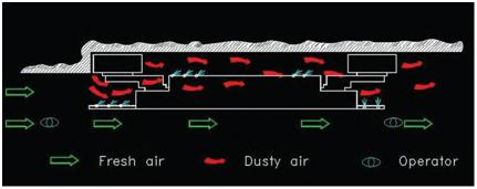 To maximize the effectiveness of the shearer-clearer system, the splitter arm should extend as far beyond the headgate drum as possible, all splitter arm sprays should be oriented with the airflow, a sufficient number of sprays should be used to prevent dust from the headgate drum from migrating to the walkway, and belting should be hung from the splitter arm to help separate face airflow and confine dust. Since the splitter arm should extend beyond the drum if possible, it should be made from sufficiently rigid steel tubing/pipe to withstand coal and rock impacts from the face. Alternately, splitter arms have been observed where springs have been mounted on the arm so that the arm can absorb a blow and bounce back into position. Since directional spray systems are attempting to move air, the operating pressure is critical and pressures of at least 150 psi should be used. Hollow-cone or venturi sprays (Figure 2) are effective for these systems. The sprays should be oriented to help move dust along the face without causing turbulence. Thus, it is not desirable to have sprays impacting the ranging arm. 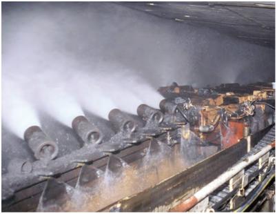 Conveyor belting suspended along the length of the splitter arm, along with the directional sprays, helps split the airflow coming down the face. The belting also provides a physical barrier between the face conveyor and walkway, which helps prevent dust from moving into the walkway. Tears and gaps in the conveyor belting greatly compromise the effectiveness of the splitter arm. Locating low-pressure, flat-fan sprays spaced evenly on the walkway side of the splitter arm and directing the sprays down the side of the belting (Figure 3) may help limit dust migration into the walkway. 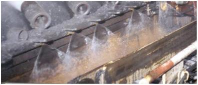 In the directional spray systems, dust-laden air is moved along the face by air spray manifolds positioned between the drums (Figure 4). These sprays promote movement of dust-laden air along the face side of the shearer to prevent migration toward the walkway. Three or four manifolds containing three to five sprays each are typically spaced along the length of the shearer body. These manifolds are either located on the face side of the shearer or on the top of the shearer close to the face. All sprays are oriented downwind. Results from a series of underground tests showed that the shearer-clearer spray system reduced operator exposure from shearer-generated dust by about 50% when cutting against face ventilation and by at least 30% when cutting with ventilation [Ruggieri et al. 1983; Jayaraman et al. 1985]. 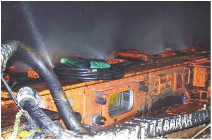 Keeping the headgate splitter arm parallel to the top of the shearer. Maintaining the position of the headgate splitter arm near parallel is critical to keeping dust from boiling out into the walkway, especially at higher-seam longwalls that are typically found at western longwall operations. During recent surveys [Rider and Colinet 2007], NIOSH personnel observed a hydraulically adjustable splitter arm that was angled down toward the pan line during head-to-tail passes, allowing respirable dust to migrate over the top of the splitter arm and into the walkway (Figure 5). Also, as mining advanced toward the headgate, NIOSH personnel noticed that a dust cloud would roll up under the splitter arm belting when the cutting drum was in the raised position and the splitter arm was angled upward (Figure 5). Positioning the splitter arm so that it is level with the shearer body and parallel to floor may prevent the dust cloud from migrating over or under the splitter arm and into the walkway. 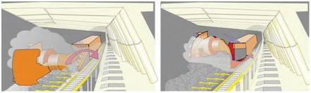 Shearer deflector plates. The main function of the hydraulically controlled shearer deflector plates (Figure 6) is to protect shearer operators from debris flying off the face. In a raised position, the deflector plates seem to enhance the directional spray system effectiveness by providing a physical barrier that helps to confine contaminated air close to the face. The deflector plates should be raised as high as face conditions allow to provide maximum protection.  Shearer deflector plates have also been equipped with water sprays mounted in the plates, which can supplement the dust control effectiveness of the shearer-clearer system. However, shearer operators must be diligent in turning off the sprays if the deflector plate is lowered. If these sprays are operational when the deflector plate is down, the spray plume is directed upward and strikes the underside of the shields. This impact creates turbulence that can cause the ventilating airstream to carry dust out into the walkway, where it may adversely affect dust levels at and downwind of the shearer. Crescent sprays. Crescent sprays (Figure 7) can be located on each ranging arm and are typically oriented inward toward the cutting drum. These sprays are located on the top and end of the ranging arm. It is important that these sprays be aimed inward toward the cutting drum and appropriately spaced to provide uniform wetting of the entire cutting zone. Crescent sprays on the headgate ranging arm should be used with caution. Sprays on the end of the headgate ranging arm are oriented into the face airflow, which can create turbulence that forces dust toward the walkway [Colinet et al. 1997]. 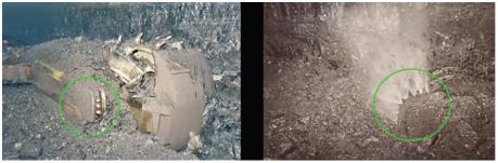 Lump breaker spray manifold. Positioning a spray manifold at the end of the lump breaker and directing the spray down toward the conveyor can provide better, more uniform wetting of the cut coal. Using larger-orifice sprays operated at pressures less than 80 psi will provide higher volumes of water per spray wetting without creating turbulence. Tailgate-side sprays. Original directional spray systems were equipped with a splitter arm with sprays on the tailgate end of the shearer to help confine shearer-generated dust near the face. These splitter arm sprays also created a clean air envelope in the walkway downwind of the shearer, potentially reducing the dust exposure of the tailgate shearer operator and jack setters advancing shields near the shearer. Although use of the tailgate-side splitter arm has declined, a similar benefit was observed at mines that installed a spray manifold on the tailgate end of the shearer (Figure 8). These sprays are oriented parallel to the tailgate ranging arm or angled slightly toward the tailgate drum and act as a water curtain confining the dust cloud near the face. It is important that these sprays confine the dust along the face and not cause excessive turbulence that could cause the dust to migrate away from the cutting drum and into the walkway. These sprays may be able to carry water a distance of 10–20 ft downwind of the shearer if aligned properly and operated with sufficient flow and pressure. They can further enhance the air split created by the shearer’s directional spray system. 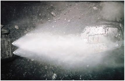 |
|
|
NIOSH [2010]. Information circular 9517. Best practices for dust control in coal mining. Morgantown, WV: U.S. Department of Health and Human Services, Centers for Disease Control and Prevention, National Institute for Occupational Safety and Health, DHHS (NIOSH) Publication No. 2010-110. Breuer H [1972]. Progress in dust and silicosis control. Glückauf 108(18):806–814. Colinet JF, Spencer ER, Jankowski RA [1997]. Status of dust control technology on U.S. longwalls. In: Ramani RV, ed. Proceedings of the Sixth International Mine Ventilation Congress. Chapter 55. Littleton, CO: Society for Mining, Metallurgy, and Exploration, Inc., pp. 345–351. Jankowski RA, Colinet JF [2000]. Update on face ventilation research for improved longwall dust control. Min Eng 52(3):45–52. Jayaraman NI, Jankowski RA, Kissell FN [1985]. Improved shearer-clearer system for double-drum shearers on longwall faces. Pittsburgh, PA: U.S. Department of the Interior, Bureau of Mines, RI 8963. NTIS No. PB 86-107844. Mundell RL et al. [1979]. Respirable dust control on longwall mining operations in the United States. In: Proceedings of the Second International Mine Ventilation Congress (Reno, NV, November 4–8, 1979). NIOSH [2008]. Work-related lung disease surveillance report, 2007. Morgantown, WV: U.S. Department of Health and Human Services, Centers for Disease Control and Prevention, National Institute for Occupational Safety and Health, DHHS (NIOSH) Publication No. 2008143a. Organiscak JA, Khair AW, Ahmad M [1996]. Studies of bit wear and respirable dust generation. In: Transactions of Society for Mining, Metallurgy, and Exploration, Inc. Vol. 298. Littleton, CO: Society for Mining, Metallurgy, and Exploration, Inc., pp. 1932–1935. Rider JP, Colinet JF [2007]. Current dust control practices on U.S. longwalls. In: Proceedings of Longwall USA (Pittsburgh, PA, June 5–7, 2007). Ruggieri SK, Muldoon TL, Schroeder W, Babbitt C, Rajan S [1983]. Optimizing water sprays for dust control on longwall shearer faces. Foster-Miller, Inc. U.S. Bureau of Mines contract J0308019. NTIS No. PB 86-205408. Shirey CA, Colinet JF, Kost JA [1985]. Dust control handbook for longwall mining operations. BCR National Laboratory. U.S. Bureau of Mines contract J0348000. NTIS No. PB86-178159/AS. Tomb TF et al. [1992]. Evaluation of respirable dust control on longwall mining operations. In: Transactions of Society for Mining, Metallurgy, and Exploration, Inc. Vol. 288. Littleton, CO: Society for Mining, Metallurgy, and Exploration, Inc., pp. 1874–1878. |
|
|
coal miners coal mining mining underground mines |