
Two Career Fire Fighters Die in Four-Alarm Fire at Two-Story Brick Structure - Missouri
 Death in the Line of Duty…A summary of a NIOSH fire fighter fatality investigation
F2002-20 Date Released: March 3, 2003
SUMMARY
On May 3, 2002, a 38-year-old male career fire fighter (Victim #1) died after he became lost and ran out of air while searching for a missing 38-year-old male career fire fighter (Victim #2) at a four-alarm, two-story structure fire. Victim #2 was identified as missing when he failed to respond to a member accountability roll call (MARC). Victim #1 reentered the structure to search for Victim #2 as part of a search-and-rescue team. Shortly thereafter, Victim #1 became lost and radioed Mayday several times. After extensive searches for both victims, they were removed from the structure and provided medical attention on the scene. They were then transported by Emergency Medical Services (EMS) to a local hospital. Victim #1 was pronounced dead on arrival, and Victim #2 was pronounced dead the following day.
NIOSH investigators concluded that, to minimize the risk of similar occurrences, fire departments should
- ensure that team continuity is maintained
- ensure that a rapid intervention team is established and in position immediately upon arrival
- ensure that the incident command system is fully implemented at the fire scene
- ensure that fire fighters, when operating on the floor above the fire, have a charged hoseline
- instruct and train fire fighters on manually activating their PASS device when they become lost, disoriented, or trapped
- ensure that a separate Incident Safety Officer (ISO), independent from the Incident Commander, is appointed
- ensure that Standard Operating Procedures (SOPs) and equipment are adequate and sufficient to support the volume of radio traffic at multiple-alarm fires
- ensure that self contained breathing apparatus (SCBAs) are properly inspected, used, and maintained to ensure they function properly when needed
INTRODUCTION
On May 3, 2002, a 38-year-old male career fire fighter (Victim #1) died after he became lost and ran out of air while searching for a 38-year-old male career fire fighter (Victim #2) at a four-alarm, two-story structure fire. On May 6, 2002, the fire department involved in the incident, and on May 8, 2002, the U.S. Fire Administration (USFA), notified the National Institute for Occupational Safety and Health (NIOSH) of the fatalities. On June 24 and July 23, 2002, the NIOSH Chief of the Trauma Investigations Section and two Occupational Safety and Health Specialists performed an on-site investigation. Meetings and interviews were conducted with the Chief and officers of the department, fire fighters, and other rescue personnel involved in this incident. Only those fire fighters and officers directly involved in this incident up to and including the removal of the victims were interviewed. NIOSH investigators also reviewed copies of the department standard operating procedures (SOPs), diagrams of the incident, training records, witness statements, run sheets, time line, coroner’s report, and SCBA tests, and they inspected the victims’ turnout gear and related equipment.
As part of the National Institute for Occupational Safety and Health (NIOSH) Fire Fighter Fatality Investigation and Prevention Program, the Respirator Branch, National Personal Protective Technology Laboratory (NPPTL) conducted an evaluation of two Survivair 4500 p.s.i. 30-minute, self-contained breathing apparatus (SCBA) at the request of the Chief of the Fire Department. These SCBA’s were last used during interior fire-fighting operations at the structure fire on May 3, 2002 by Victim #1 and Victim #2. A summary of the NPPTL report is attached as Appendix I.
Training and Experience
The career fire department involved in this incident has 36 responding apparatus, 30 stations, 682 uniformed fire fighters and serves a population of approximately 325,000 in an area of about 62 square miles. Victim #1 had been a fire fighter for 11 years, 5 months, and Victim #2 had been a fire fighter for 11 years, 10 months. Both had successfully completed all state-required fire academy training, which complies with NFPA Level I and II.
Equipment
First Alarm
Engine Company 1 (E-1) – Captain, 3 Fire Fighters (FFs)
Engine Company 29 (E-29) – Captain, 3 FFs
Engine Company 7 (EC-7) – Captain, 3 FFs
Engine Company 11 (EC-11) – Captain, 3 FFs
Hook and Ladder 6 (HL-6) – Captain, 3 FFs
Rescue-1* – Captain, 5 FFs, 2 riders
802 Battalion Chief (BC-1) – Incident Command (IC)
804 Battalion Chief (BC-2)
Acting 810 Battalion Chief
Second Alarm
Engine Company 14 (E-14) – Captain, 3 FFs
Hook and Ladder 2 (HL-2) – Captain, 3 FFs
Engine Company 2 (EC-2) – Captain, 3 FFs
Engine Company 32 (EC-32)- Captain, 3 FFs
900 Command Post
821 Fire Investigator
Acting 803 Captain
Third Alarm
Engine Company 9 – Captain, 3 FFs
Engine Company 4 – Captain, 3 FFs
Engine Company 17 – Captain, 3 FFs
Squad 2 – Captain, 5 FFs
Hook and Ladder 4 – Captain, 3 FFs
805 Battalion Chief
820 Chief Investigator
Fire Chief
Fourth Alarm
Engine Company 22 – Captain, 3 FFs
Engine Company 12 – Captain, 3 FFs
Engine Company 36 – Captain, 3 FFs
Truck 15 – Captain, 3 FFs
* Both victims were assigned to Rescue-1.
Structure
The two-story commercial brick structure was of ordinary construction, situated in a connected row with several other properties with variable roof heights. The roof of the involved structure was relatively flat and sealed with built-up roofing materials. There were two entrances on the A-side at the ground level (Photo 1). The west entrance led to the upper level via a stairway, and the east entrance accessed the lower level through the doorway. Both entrances were secured by a padlocked swinging wrought-iron gate/door. There were no man doors noted at the lower level from the B- or D-sides (Diagram 1); however, there was one man door on the west end of C-side and a gated garage door at the east end of the C-side (Photo 2).
There were five openings on the second level, D-side (one being partially bricked, with the remainder being closed with block glass), two windows on the first level, A-side, and three relatively tall windows on the second level, A-side (Photo 1). Other than the block glass window on the D-side (Photo 3), all windows were either made of plexi-glass or sealed substantially with wood. The structure was uninhabited at the time of the incident.
The total area of the building was 3,150 square feet. The first level consisted of two rooms for a total of 1,575 square feet. The front room of the structure was approximately 300 square feet. The second level consisted of four rooms, and was also 1,575 square feet. The stairway access broke off into two entrances at the second level, one leading to the north and one to the east. (Diagrams)
INVESTIGATION
On May 3, 2002, at about 2102 hours, Central Dispatch (Fire Alarm) received a telephone call of a potential fire at a commercial property. Fire Alarm dispatched the first alarm. Crews arrived at the scene at 2105 hours. On arrival at 2108, the Incident Commander observed fire fighters making entry to the upper and lower levels of the structure from the A-side, which had light gray smoke coming from the front. Initial size-up indicated that the fire was at the first level. The IC called for police traffic control and assigned E-7 to be backup water for E-1. E-1 had one 1¾-inch pre-connect pulled for entry into the lower-level entrance (east). E-29 was assigned to back up HL-6.
Fire fighters from Rescue 1, E-1, E-7, and E-29 forced entry to the west entrance upper-level access door (on the left at ground level) and progressed up the stairway to the second level to conduct a primary search, check for fire extension, and to ventilate the windows. At the same time, a fire fighter from E-1 pulled a “TNT” force-entry tool and forced entry to the east entrance lower-level access door (on the right at ground level). The crew from E-1 then advanced 1¾-inch hoseline through the east entryway to the first level, backed-up by the crew from E-11. A fire fighter from E-1 initially had the nozzle but handed it off to the Captain of E-1. A positive pressure ventilation (PPV) fan was set in the doorway of the first (west) entrance to provide ventilation. When the team hit the fire with the hose line at the first level, it appeared as though they had knocked the fire down immediately. During this fire attack, several fire fighters noted that there were holes in the ceiling of the first floor, and they noted embers and fire when ceiling tile was pulled.
After it had appeared that fire had been knocked down, the crews believed that the fire had extended to the second level. The crews from E-1 and E-11(without the Captain from E-11) pulled the handline out of the first floor entry and advanced to the upper-level entrance and up the stairs to the second floor.
At approximately 2114, the Captain from E-11 became separated when he progressed further into the building as the rest of the crew pulled out. He had reportedly opened an overhead roll-up type garage door that accessed the outside at the first level (C-side). As he turned around, he saw the fire flare up and roll across the ceiling toward him. A van was parked by the garage door, but did not obstruct his movement. The smoke, fire, and heat significantly intensified at this time, and the Captain from E-11 could not retreat back through the building. When he attempted to leave the structure through the garage door opening, he realized that a lock on a metal security gate outside of the garage door prevented his escape (Photo 2). Using channel 2, the Captain from E-11 called for the IC twice with no response and BC#2 once with no response. He then called Fire Alarm and stated that he was forced to the floor by fire and heat and needed extrication out the back of the structure by the garage door. The Captain from Rescue-1 was in the immediate area behind the structure. After repeated failed attempts to cut the lock on the gate, the Captain from Rescue-1 enlisted the aid of two citizens who helped him pull the gate up and partially off its hinges. At the same time, two 1¾-inch hoselines were pulled off of E-1 and working at the A-side. Simultaneously, on the upper level, fire fighters from Rescue-1, E-1, E-7, E-11, and E-29 were checking for fire extension and began ventilating the windows. According to radio transmissions, Fire Alarm called the IC at 2116 and informed him that he had a fire fighter trapped (Captain of E-11) in the rear of the building in the garage area by the overhead garage door. After extrication of the Captain at approximately 2118, the IC called for all fire fighters from the first level to be accounted for, and at that time it was believed that all members were accounted for. The IC instructed the Captain from E-29 to advance a 2½-inch hoseline from E-1 A-side to the rear of the structure (C-side). A 2½-inch hoseline was also pulled off E-11 and pulled to the C-side.
A fire fighter from E-29 who was ventilating windows on the second level saw and heard Victim #2 behind him, and he stated that Victim #2 appeared to be lost. Visibility was very poor at this time, and it was getting very hot. Simultaneously, at 2118, the IC conducted a member accountability roll call (MARC), where all fire fighters are to exit the building and report to their companies for accountability. The fire fighter told Victim #2 that he knew the way out, and they began crawling toward where he thought the stairway was. He then lost Victim #2 and started to feel as though he was becoming lost himself. He backtracked the way he had come and found Victim #2 lying facedown and unresponsive on the floor. He attempted to pull the victim toward where he thought the stairs were, but he was unsuccessful. He immediately radioed for help. According to transcript tapes, he called for help and Mayday several times. [NOTE: The audio transcript tapes illustrated that radio traffic was very congested at times during this incident.] When he began to run out of air and it was apparent that no one had heard his distress calls, he was forced to leave Victim #2. As he made it to the stairs, he ran out of air and his mask began sucking to his face. He escaped the building at approximately 2120 and yelled to BC-2 that a fire fighter was down on the second floor. He then ran to have his SCBA tank replaced.
The fire fighter did not reenter the structure, but a search party was formed and several other fire fighters (including Victim #1) reentered the second level of the building to search for Victim #2. Victim #2 was found by a fellow fire fighter from Rescue-1. Several other fire fighters assisted in his removal down the stairs. Victim #2 was immediately provided emergency medical treatment.
The captain from Rescue-1 took another head count of his men and, realizing that Victim #1 was now missing, informed the IC. Another search party was formed and the building was reentered to the second level. A second 1¾-inch line was advanced up to the second floor just as a personal alert safety system (PASS) device was heard in the rear of the structure (Victim #1). A fire fighter on the rescue team located Victim #1 near the D-side. At this time conditions had seriously deteriorated and the intense heat drove some of the fire fighters back. Fire fighters brought a ladder to the adjacent one-story building on the C-side, and they made entry through a window on the D-side. The window was heavily boarded up, so the wood had to be forcefully opened. Victim #1 was found in the prone position and removed through the window of the second level, D-side, onto the adjoining one-story building. Victim #1 was then brought to the lower level in a stokes basket by HL-2. Emergency medical treatment was provided to Victim #1. Both victims were immediately transported to a local hospital via EMS. It was later determined that Victim #1 was missing for approximately 29 minutes, and Victim #2 was missing for approximately 20 minutes.
CAUSE OF DEATH
According to the coroner’s report, the cause of death for both victims was smoke inhalation. The carbon monoxide level in the blood was noted to be less that 10% in Victim #1, and 47.9% in Victim #2. Victim #1 had third-degree thermal injury over 40% of his body, and Victim #2 had third-degree thermal injury over 18% of his body surface area.
RECOMMENDATIONS/DISCUSSION
Recommendation #1: Fire Departments should ensure that team continuity is maintained. 1, 2
Discussion: Team continuity involves knowing who is on your team and who is the team leader, staying within visual contact at all times (if visibility is obscured then teams should remain within touch or voice distance of each other), communicating your needs and observations to the team leader, rotating to rehab and staging as a team, and watching your other team members (practice a strong “buddy-care” approach). These key factors help to reduce serious injury or even death resulting from the risks involved in fire-fighting operations by providing personnel with the added safety net of fellow team members. As teams enter a hazardous environment together, they should leave together to ensure that team continuity is maintained.
Recommendation #2: Fire departments should ensure that a rapid intervention team is established and in position immediately upon arrival. 3–5
Discussion: A Rapid Intervention Team (RIT) should respond to every working structure fire. The team should report to the IC and remain at the staging area until an intervention is required to rescue a fire fighter. The RIT should have all the tools necessary to complete the job-e.g., a search rope, rescue rope, first-aid kit, and a resuscitator to use in case a fire fighter needs assistance. These teams can intervene quickly to rescue fire fighters who become disoriented, lost in smoke-filled environments, trapped by fire, involved in structural collapse, or run out of air.
Recommendation #3: Fire Departments should ensure that the incident command system is fully implemented at the fire scene. 6
Discussion: The Incident Command System (ICS) defines the roles and responsibilities to be assumed by personnel and the operating procedures to be used in the management and direction of emergency incidents and other functions. The Incident Commander (IC) is the individual with overall responsibility to implement and oversee the system.
The following functions are the responsibility of the IC, which include, but are not limited to
Assumption, confirmation, and position of command. After the IC arrives on the fireground and assumes command, a stationary command post on the exterior of the fire building should be established. Command positioning becomes a critical factor in the overall effectiveness of the incident. A strategic level of command can only be produced if the IC is in a stationary command-post position. The command post should be situated in a conspicuous location which affords the IC a good view of the fire building and surrounding area. Ideally, it would offer a view of two sides of the fire building. Advantages of a command post are (1) stationary position, (2) a relatively quiet place in which to think and make decisions, and (3) a vantage point to oversee the operation. A stationary command post also offers the potential for improved lighting, protection from weather, space for additional staff, and access to more powerful mobile radios, reference and preplanning materials, and portable computers (in some instances).
Situation evaluation. The IC is the only person who has the exterior, stationary, command-post-position advantage that allows current and forecasted information to be received, processed, evaluated, and then translated into a series of decisions that control the position and function of the fire fighters working in and around the hazard zone. This information management function becomes a major reason why the IC should stay at the command post. It is difficult for an IC to receive, decipher, and then react effectively to reports from all over the incident site if he/she is moving around, in proximity to operational noise, distracted by direct face-to-face communications with fire fighters, and limited to a portable radio as opposed to a more powerful mobile radio.
Initiate, maintain, and control communications. It is the IC’s responsibility to initiate, maintain, and control effective incident communications. This communications function is critical to safe and effective incident operations because it is the means by which the IC and all the other incident participants stay connected. Being able to effectively communicate becomes the major tool the IC uses to exchange information and to create effective action. The IC should use the stationary command-post advantage to maintain continuous and clear communications.
Deployment. The deployment function requires the IC to provide and manage a steady, adequate, and timely stream of appropriate resources. Typically, the IC logs the arriving units into the inventory and tracking system on a tactical worksheet in the stationary command post. The IC also enters the units into a standard accountability system that tracks where companies/crews are located in the hazard zone.
Strategy/incident action planning. A critical responsibility of the IC is to identify and manage the overall incident strategy (offensive or defensive). The IC must continually evaluate the relationship between the level of hazards present and the basic capability of the safety system to protect fire fighters from those hazards. The hazards present at structural fires involve structural collapse, thermal and toxic insult, becoming trapped and running out of air, and becoming disoriented, lost, and running out of air. The conditions present at this incident included a seemingly vacant building with two levels, very few accessible openings to the outside, energized overhead power lines impeding access to the second level from the rear, and holes in the second-level floor. These conditions, combined with an active fire, created an environment with numerous hazards.
Recommendation #4: Fire departments should ensure that fire fighters, when operating on the floor above the fire, have a charged hoseline. 7
Discussion: It is a good practice to have a charged hoseline when operating on the floor above the fire. Where there is risk of extension to concealed spaces and attics, additional precautionary lines are needed at each of these areas. Backup lines may also be needed in other areas above the fire. In this incident, several fire fighters made it to the second floor to perform truck operations (ventilate and search for fire extension) above the fire and were not equipped with a charged handline.
Recommendation #5: Fire departments should instruct and train fire fighters on manually activating their PASS device when they become lost, disoriented, or trapped. 1
Discussion: When a fire fighter becomes lost or disoriented, a few simple steps can facilitate a rescue and reduce the chance of injury. The first step is the radio transmission of the Mayday situation, followed by the fire fighter providing the RIT and IC with clues as to his last known location. The fire fighter’s second step involves manually activating the PASS device. The final step requires the fire fighter to remain calm (conserving air), stay in radio contact with command and the RIT, and to survey the surroundings in an attempt to gain a bearing of direction or potential escape routes. It is important that if the fire fighter is not in immediate danger of fire impingement or collapse, that he remains in the safe area and moves as little as possible. This will conserve air and possibly help the RIT find the fire fighter more quickly than if the fire fighter is constantly moving. These steps should be incorporated into the department’s standard operating procedures with fire fighters trained on those procedures. Although fire fighters identified the fact that Victim #1’s PASS was activating, investigators were unable to determine, through interviews or equipment examination, whether Victim #2’s PASS device had gone into alarm mode.
Recommendation #6: Fire departments should ensure that a separate Incident Safety Officer (ISO), independent from the Incident Commander, is appointed. 8–11
Discussion: According to NFPA 1561, paragraph 4-1.1, “the Incident Commander (IC) shall be responsible for the overall coordination and direction of all activities at an incident. This shall include overall responsibility for the safety and health of all personnel and for other persons operating within the incident management system. While the IC is in overall command at the scene, certain functions must be delegated to ensure adequate scene management is accomplished.” According to NFPA 1500, paragraph 6-1.3, “as incidents escalate in size and complexity, the IC shall divide the incident into tactical-level management units and assign an ISO to assess the incident scene for hazards or potential hazards.” The most effective ISOs are those who operate as a consultant to the IC. The ISO establishes a relationship with the IC by asking what the action plan is, followed by a summary of the current situation status and resource status. With this information, the ISO can collect more information in the form of a reconnaissance or 360-degree size-up of the incident. With this additional information, the ISO can report concerns and possible solutions to the IC. During this incident, the IC was also acting as the Safety Officer and thus was limited in being able to perform the additional functions of a separate ISO.
Recommendation #7: Fire departments should ensure that Standard Operating Procedures (SOPs) and equipment are adequate and sufficient to support the volume of radio traffic at multiple-alarm fires. 9
Discussion: At times, fireground communications become ineffective because of congested radio traffic and inadequate radio equipment on the fireground. Although the IC had Central Dispatch clear the radio channel for emergency traffic, most radio operators continued to use the same channel. Standard operating procedures (SOPs) should be written and implemented, and communications equipment should be of sufficient quantity and quality to support the volume of communications encountered at the fire scene. In the event of Maydays or emergencies on the fireground, all fire fighters should switch radio operations to a new frequency or other channels. This would open the main channel for communication in case of an emergency or lost fire fighters. In this case, some fire fighters switched channels and others did not.
Recommendation #8: Fire departments should ensure that self contained breathing apparatus (SCBAs) are properly inspected, used, and maintained to ensure they function properly when needed. 12, 13
Discussion: It is rare for a SCBA respirator performance evaluation, in and of itself, to point to causes of a fatality. In this case, it was not possible to determine if the deficiencies discovered during the testing of the Unit #2 SCBA existed prior to the victim’s death or were sustained subsequent to his death from fire or recovery efforts, or handling of the equipment prior to and during shipping to NIOSH. Regardless, NFPA 1404 contains general guidelines that all fire departments should follow to ensure that all in-service SCBAs are in good working order and will function properly when needed. An SCBA will only provide the highest level of protection when it is properly serviced and maintained. Both NFPA 1404, (Chapter 5-1.4) and the Occupational Safety and Health Administration (OSHA) Respirator Standard (29CFR 1910.134(h)(3)(i)(A) require the SCBA to be inspected prior to use. This inspection should include a functional check to ensure that the regulator, low-air alarm, bypass valve, and other features of the SCBA are working properly. Additionally, NFPA 1404, Chapter 6-2.1, and OSHA 29CFR 1910(c)(1)(v) require a preventive maintenance program to be in place to prevent SCBA malfunction and equipment failure during use.
REFERENCES
- Fire Fighter’s Handbook [2000]. Essentials of fire fighting and emergency response. New York: Delmar Publishers.
- Morris G, Gary P, Brunacini N, Whaley L [1994]. Fireground accountability: The Phoenix System. Fire Engineering, 147(4) 45-61.
- Dunn V [1988]. Collapse of burning buildings, a guide to fire ground safety. Saddle Brook, NJ: Fire Engineering Books and Videos.
- Kipp JD, Loflin ME [1996]. Emergency incident risk management: safety and health perspective. New York: Van Nostrand Reinhold Publishing.
- Norman [1998]. Fire officer’s handbook of tactics. Saddle Brook, NJ: Fire Engineering Books and Videos.
- Brunacini, AV [2000]. Written expert review of NIOSH FACE report 98F-47 of August 21, 2000, from AV Brunacini to R Braddee, Division of Safety Research, National Institute for Occupational Safety and Health, Centers for Disease Control and Prevention, Public Health Service, U.S. Department of Health and Human Services.
- Dunn V [1992]. Safety and survival on the fire ground. Saddle Brook, NJ: Fire Engineering Books & Videos.
- Smoke CH [1999]. Company officer. New York: Delmar Publishers.
- NFPA [1995]. NFPA 1561, standard on fire department incident management system. Quincy, MA: National Fire Protection Association.
- NFPA [1997]. NFPA 1521, standard for fire department safety officer. Quincy, MA: National Fire Protection Association.
- Dodson DW [1999]. Fire department: incident safety officer. New York: Delmar Publishers.
- NFPA [2001]. NFPA 1404, standard for a fire department self-contained breathing apparatus program. Quincy, MA: National Fire Protection Association.
- OSHA [1998]. 29 CFR Part 1910.134, respiratory protection; Final Rule. US Department of Labor. Federal Register, Vol 63, No. 5.
INVESTIGATOR INFORMATION
This investigation was conducted by Robert Koedam, Chief of the Trauma Investigations Section, and Safety and Occupational Health Specialists Mark McFall and Jay Tarley, Surveillance and Field Investigations Branch, Division of Safety Research.
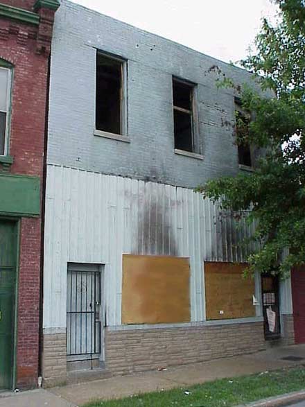
Photo 1. A-Side
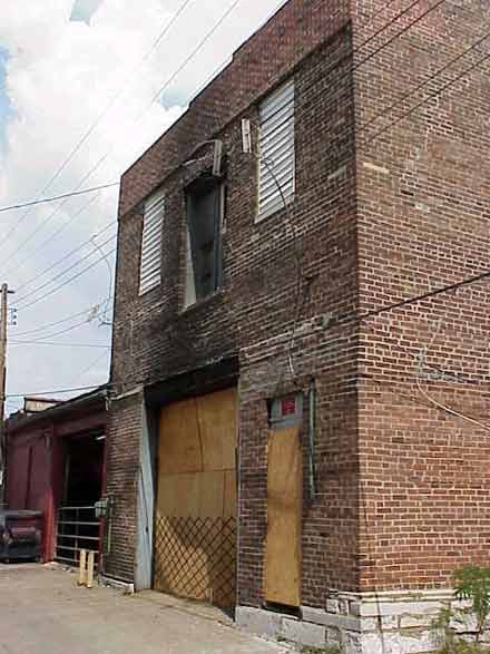
Photo 2. C-Side
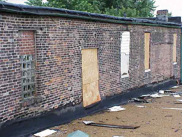
Photo 3. D-Side
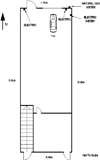
Diagram 1. First Level
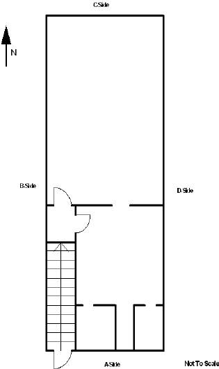
Diagram 2. Second Level
APPENDIX I: NIOSH SCBA Test Report

Status Investigation Report of Two
Self-Contained Breathing Apparatus
Missouri
NIOSH Task No. TN-12448
December 11, 2002
Disclaimer
| The purpose of Respirator Status Investigations is to determine the conformance of each respirator to the NIOSH approval requirements found in Title 42, Code of Federal Regulations, Part 84 (42 CFR 84). A number of performance tests are selected from the complete list of Part 84 requirements and each respirator is tested in its “as received” condition to determine its conformance to those performance requirements. Each respirator is also inspected to determine its conformance to the quality assurance documentation on file at NIOSH.
In order to gain additional information about its overall performance, each respirator may also be subjected to other recognized test parameters, such as National Fire Protection Association (NFPA) consensus standards. While the test results give an indication of the respirator’s conformance to the NFPA approval requirements, NIOSH does not actively correlate the test results from its NFPA test equipment with those of the NFPA. Thus, the NFPA test results are provided for information purposes only. Selected tests are conducted only after it has been determined that each respirator is in a condition that is safe to be pressurized, handled, and tested. Respirators whose condition has deteriorated to the point where the health and safety of NIOSH personnel and/or property is at risk will not be tested. |
Investigator Information
The SCBA inspections were conducted by and this report was written by Vance Kochenderfer, Quality Assurance Specialist, Respirator Branch, National Personal Protective Technology Laboratory, National Institute for Occupational Safety and Health, located in Bruceton, Pennsylvania.
Status Investigation Report of Two
Self-Contained Breathing Apparatus
Missouri
NIOSH Task No. TN-12448
Background
As part of the National Institute for Occupational Safety and Health (NIOSH) Fire Fighter Fatality Investigation and Prevention Program, the Respirator Branch agreed to examine and evaluate two Survivair 4500 psi, 30-minute, self-contained breathing apparatus (SCBA). The Fire Department reported that the SCBA were last used during interior firefighting operations at a structure fire on May 3, 2002.
This SCBA status investigation was assigned NIOSH Task Number TN-12448. The Fire Department was advised that NIOSH would provide a written report of the inspections and any applicable test results.
The SCBA, sealed in corrugated cardboard boxes, were delivered to the NIOSH Appalachian Laboratory for Occupational Safety and Health (ALOSH) in Morgantown, West Virginia on May 7, 2002. Upon arrival, the sealed packages were taken to the Firefighter SCBA Evaluation Lab (Room 1520) and stored under lock until the time of the evaluation.
SCBA Inspection
The first package from the Fire Department was opened, and the SCBA inspection was initiated on May 9, 2002, in Room 1520 of the ALOSH Building. The inspection of Unit #1 was completed that same day. Unit #2 was inspected on May 16, 2002. The SCBA were inspected by Vance Kochenderfer, Quality Assurance Specialist, of the Respirator Branch, National Personal Protective Technology Laboratory (NPPTL), NIOSH. The SCBA were examined, component by component, in the condition as received to determine their conformance to the NIOSH-approved configuration. The entire inspection process was videotaped. The SCBA were identified as the Survivair Panther™ model.
An unusual observation made for both units was that the fabric components (hood, head harness, and neck strap) of the facepiece were damp. The facepieces were allowed to dry before testing was performed. The facepiece lens of Unit #1 had an inch-long crack. In addition, the backframe of Unit #1 was severely cracked. Discussions with the Fire Department indicate that this may have occurred during attempts to rescue the wearer.
Personal Alert Safety System (PASS) Device
A Personal Alert Safety System (PASS) device was incorporated into the pneumatics of each SCBA. During the inspection, the PASS devices were activated both manually and automatically. Although the units appeared to function normally, they were not tested against the requirements of NFPA 1982, Standard on Personal Alert Safety Systems (PASS), 1998 Edition. Because NIOSH does not certify PASS devices, no further testing or evaluations were conducted on the PASS units.
SCBA Testing
The purpose of the testing was to determine the SCBA’s conformance to the approval performance requirements of Title 42, Code of Federal Regulations, Part 84 (42 CFR 84). Further testing was conducted to provide an indication of the SCBA’s conformance to the National Fire Protection Association (NFPA) Air Flow Performance requirements of NFPA 1981, Standard on Open-Circuit Self-Contained Breathing Apparatus for the Fire Service, 1997 Edition.
The following performance tests were conducted on the SCBA:
NIOSH SCBA Certification Tests (in accordance with the performance requirements of 42 CFR 84):
1. Positive Pressure Test [42 CFR 84.70(a)(2)(ii)]
2. Rated Service Time Test (duration) [42 CFR 84.95]
3. Gas Flow Test [42 CFR 84.93]
4. Exhalation Breathing Resistance Test [42 CFR 84.91(c)]
5. Static Facepiece Pressure Test [42 CFR 84.91(d)]
6. Remaining Service Life Indicator Test (low-air alarm) [42 CFR 84.83(f)]
National Fire Protection Association (NFPA) Tests (in accordance with NFPA 1981, 1997 Edition):
7. Air Flow Performance Test [NFPA 1981, Chapter 6, 6-1]
Testing of Unit #1 was initiated on May 13, 2002. Five performance tests were completed that day. The Exhalation Breathing Resistance Test and Static Facepiece Pressure Test were conducted on May 14, 2002. Testing of Unit #2 was initiated on May 21, 2002. Five performance tests were completed that day. The Exhalation Breathing Resistance Test and Static Facepiece Pressure Test were conducted on May 22, 2002. All testing was videotaped with the exception of the Exhalation Breathing Resistance Tests and Static Facepiece Pressure Tests.
Unit #1 met the requirements of all tests. However, while the low-air warning bell functioned properly during the Remaining Service Life Indicator Test, it did not ring during the Rated Service Time test. While this does not constitute a failure, it may indicate that maintenance is required.
Unit #2 failed the Rated Service Time Test and Positive Pressure Test. In addition, the low-air gauge warning light did not activate during any tests, failing the Remaining Service Life Indicator Test.
When Unit #2 was initially subjected to the Rated Service Time Test/Positive Pressure Test, the exhalation valve was stuck closed. The valve was then freed by manually opening the valve and the test re-run. Early in the Rated Service Time Test, the low-air warning bell began sounding abnormally, making a buzzing noise. Later, at the time when it was expected to activate, the bell sounded normally but erratically.
Summary and Conclusions
Two SCBA were submitted to NIOSH by the Fire Department for evaluation. The two SCBA were delivered to NIOSH on May 7, 2002. Unit #1 was inspected on May 9, 2002. Unit #2 was inspected on May 16, 2002. The two units were identified as Survivair Panther™, 30-minute, 4500 psi, SCBA (NIOSH approval number TC-13F-284). Both were labeled as compliant to the 1997 edition of NFPA 1981. Despite damage to the backframe of Unit #1, both SCBA were determined to be in a condition safe for testing.
The two units were each subjected to a series of seven performance tests. Testing began on May 13, 2002, and was completed on May 22, 2002. Unit #1 met the requirements of all six selected NIOSH tests performed. Unit #1 also met the facepiece pressure requirements of the NFPA Air Flow Performance Test. No maintenance or repair work was performed on Unit #1 at any time. Initially, the exhalation valve of Unit #2 was stuck closed. Testing was resumed after the valve was freed. Unit #2 failed to meet the requirements of the Rated Service Time Test and Positive Pressure Test, and the gauge light failed the Remaining Service Life Indicator Test. Unit #2 met the facepiece pressure requirements of the NFPA Air Flow Performance Test.
In light of the information obtained during this investigation, the Institute has proposed no further action at this time. Following inspection and testing, the SCBA were returned to the packages in which they were received and stored under lock in Room 1520 at the NIOSH facility in Morgantown, West Virginia. The packages were moved to Building 108 at the NIOSH facility in Bruceton, Pennsylvania, in connection with the transfer of the National Personal Protective Technology Laboratory to that location. They were secured there pending return to the Fire Department.
If the SCBA are to be placed back in service, they should be repaired, inspected, and tested by a qualified service technician. In particular, Unit #2 is non-conforming and cannot be used unless it is restored to proper performance. Special attention should be paid to the low-air warning bells of both units. The facepiece lens of Unit #1 should also be replaced. While in storage, the cylinders of both units have become due for inspection and hydrostatic testing by a Department of Transportation authorized retester before the cylinders can be returned to service.
National Personal Protective Technology Laboratory/Respirator Branch/Quality Assurance Section
Respirator Field Problem
Incoming Inspection Report Summary – Unit #1
| Task Number: | TN-12448 | ||
| Date Received: | 7 May 2002 | ||
| Date Inspected: | 9 May 2002 | Description: | Fatality |
| Manufacturer: | Survivair | Inspected by: | Vance Kochenderfer |
| Approval Number: | TC-13F-284 | SCBA Type: | Open Circuit, Pressure-Demand |
Identification
The SCBA designated as Unit #1 bears the following markings – Facepiece: “1335RM“; Regulator: “SOIB“; Backpack: “SQ 1B”
Components and Observations – Unit #1
NOTE: All references to “right” or “left” are from the user’s perspective.
- Facepiece
The facepiece appears to be a Survivair TwentyTwenty facepiece assembly which consists of a rubber facepiece seal, lens, lens frame, and mesh head harness. A thermal protective hood is attached to the facepiece with snaps. Also attached to the facepiece is a neck strap. There is a nosecup assembly installed. Overall the facepiece is in very good condition. The hood, head harness, and neck strap are all damp.The exterior of the facepiece lens has many scratches. Visibility through the lens is fair. There is a crack, approximately one inch in length, in the lens above the regulator connection point. The black lens rim is in very good shape. The rim is tightly fitted to the facepiece seal. Both of the rim mounting screws are fully seated. There are no gaps between the rim and the facepiece seal or between the lens and the facepiece seal. The letter “X” is molded into the top of the rim just to the left of the center head harness attachment strap.
The assembly that houses the second-stage regulator port, speaking diaphragm, and exhalation valve sub-assemblies is fully intact. Hand-engraved on the top of the housing are the figures “1335RM.” Molded into the rim around the regulator port are “962060 AIR KLIC P” and “EN 136“. The red rubber o-ring is in place and in good condition. The speaking diaphragm is installed and appears undamaged. The code “MMFA0240” is factory-engraved on the interior of the assembly. A label appears on the inside chin area of the facepiece and reads as follows:

The black silicone rubber facepiece seal is completely intact and pliable. There are no cuts, deformities, or any signs of damage. Although in excellent condition, it is quite dirty. A large letter “M” is molded into the upper portion of the seal, indicating this is a medium-sized facepiece. The part number “962167” is molded into the interior chin area of the seal. There is a round date code molded into the left chin area on the interior surface of the seal. This code is somewhat difficult to read; although it indicates that the seal was molded in 1999, it is unclear in which month.
There is a translucent nosecup assembly installed in the facepiece. The nosecup is firmly attached to the facepiece assembly. It is also dirty, with a gritty red substance also present on the interior of the faceseal. Two inhalation valves are properly installed and in good shape. The letter “S” is molded into the nosecup along with the part number “962144” and a circular-shaped date code that indicates the nosecup was manufactured in October 1999.
A black mesh head harness is secured to the facepiece assembly with non-adjustable straps at three attachment points. An adjustable elastic strap secures the lower portions of the harness to the facepiece chin area. All five attachments are securely fastened to assembly. The adjustable harness strap has retained much of its elasticity. The mesh fabric and all straps are very pliable. There are no signs of exposure to excessive heat or flame. The two adjustment buckles operate smoothly.
The neck strap attached to the facepiece near the regulator port is in good shape. It is securely attached to the facepiece assembly. The thermal protective hood is also in good condition and has no burns or tears. It is soiled with soot.
- Air Pressure Regulator
The exterior of the facepiece-mounted second-stage air pressure regulator assembly shows signs of use and wear. The rubber covering shows some minor damage, and is torn slightly at the regulator shut-off (donning) switch. Attempts to engage and disengage the donning switch indicate that it is inoperable. The letters “SOIB” are hand-engraved on the left side of the regulator. The mostly-legible serial number “99112??271” is factory-engraved into the unit on the facepiece side, where the two indistinct characters appear to be “98.” A new regulator examined for comparison had a part number/lot number label affixed and anti-tamper sealant on the three screws; neither of these are present on this unit’s regulator.The stainless steel screen and plastic grill covering the regulator outlet are intact. The two blue regulator release buttons operate properly and spring-return to their original positions when depressed.
The red regulator bypass valve was found to be almost fully closed. The valve operator is dirty and slightly worn. The regulator bypass valve turns smoothly. There is a directional arrow along with the word “AIR” molded into the regulator bypass valve operator. The valve was fully closed before testing was performed.
- Low-Pressure Hoses
The low-pressure hoses that lead from the Personal Alert Safety System (PASS) device to the regulator and from the first-stage air pressure reducer to the PASS unit appear to be in good working condition. The entire lengths of both sections of the hose are pliable and free of major cuts and abrasions.The section of hose between the PASS device and the regulator attaches to the PASS device via a quick-disconnect fitting. The quick-disconnect fitting couples and uncouples properly. The male portion of the fitting is stamped with “CEJN 341 5352.” The crimp-on fitting at this end of the hose is stamped “C9.” The female side of the quick-disconnect fitting is attached to the PASS device and has the Survivair logo and the word “Survivair” engraved. At the opposite end of the hose, a swivel fitting attaches the hose to the regulator. The swivel operates freely.
The section of hose between the first-stage air pressure reducer and the PASS device is routed properly through the backpack and shoulder harness. The fittings at each end of the hose are securely attached. The swivel fitting connecting the hose to the pressure reducer operates freely.
- PASS Device
The integrated PASS device is intact and there are no signs of damage or exposure to excessive heat. The speakers on each side of the unit are intact and unobstructed. Although the clear plastic lens is dirty, the lights are visible underneath. The front of the device displays the Survivair logo and the word “COMPASS“. Molded into the back of the unit is an SEI certification label indicating the PASS complies with NFPA 1982. An intrinsic safety label is molded into the left side of the unit. The red control button for the unit is on the opposite side. The button operates properly.NOTE: During the inspection, the PASS device was manually activated using the red control button on the side of the unit. The PASS operated properly in this mode and was reset. The armed device was then placed at rest on the inspection table. The alarm automatically activated after approximately 20 seconds and was then reset and disarmed. It should also be noted that the device appeared to operate properly when pressurized during performance testing. During testing, the device repeatedly activated due to lack of motion, and each time, the device was reset via motion or by way of the control button.
- Air Pressure Reducer
The air pressure reducer housing is in very good condition but dirty. The bolts that secure the low pressure side to the high pressure side are intact and fully seated. The serial number “99033125617quot; is stamped into the base of the unit. The low-air alarm bell is shiny and undamaged except for minor scratches on the exterior. What appears to be a piece of a leaf is trapped between the striker and the bell. The green handwheel on the cylinder coupler turns freely. The interior threads are undamaged. The o-ring on the end of the nipple is in place. The o-ring is slightly dirty, but undamaged. - Remote Air Pressure Gauge
This SCBA is equipped with a remote cylinder pressure gauge. The overall condition of the remote air pressure gauge is very good. The gauge body is covered with a protective rubber boot. The gauge turns freely at the swivel fitting. The gauge lens is slightly scratched, but the 4500 psig gauge is legible and reads empty. The low-air warning light and lens are intact. Removing the protective boot reveals an intrinsic safety label on the back of the gauge and a silver label on top, the printing of which is no longer visible.The high pressure hose which leads from the first-stage air pressure reducer to the remote air pressure gauge is pliable and in good condition. It is properly routed through the right shoulder strap. The hose is printed with “WARNING DO NOT EXCEED 5000 PSI/350 BAR EN-250.” The figures “C9” are stamped into the crimp-on fitting at the pressure reducer end. The crimp-on fitting at the gauge end is stamped with the number “9806 18.” The swivel fitting connecting the host to the pressure reducer turns freely.
- Backframe and Harness Assembly
The black composite plastic backpack frame has sustained significant damage. A long crack extends from inside the right side handle down to the left of the cylinder bracket. A lateral crack extends left from this crack. The portion of the backframe which attaches to the left side waistbelt is completely broken away from the rest of the backframe. The word “SURVIVAIR” is molded into a handle on each side of the backpack. The Survivair logo is molded into the pad for the air cylinder. The identifier “SQ 1B” is hand-painted in white near the top on the front side of the backpack.The NIOSH approval label on the back right side of the backframe is partially covered in soot, but is mostly intact and legible. The label indicates that this 30-minute, 4500 psi SCBA configuration has been issued NIOSH approval number TC-13F-284. An SEI certification label on the back left side is also mostly intact and readable. The label indicates that this SCBA meets the requirements of NFPA 1981, 1997 Edition.
There is a barcode label near the SEI label that displays the number “HMFA0005“. There is a part number label near the base of the frame that is illegible.
The cylinder strap is dirty but otherwise in good condition. The buckle operates properly. The cradle pad is in good condition, as is the cylinder support bracket at the bottom of the backframe.
The right shoulder strap is in very good condition. The shoulder padding is flexible. The fabric sleeve over the left shoulder strap has sustained some damage from heat or fire. Otherwise, the strap is in good condition. Both shoulder straps are securely attached to the backframe. All hoses are properly routed through the straps and hose mounts. The adjustment straps are in good shape. Both adjustment buckles operate properly.
The waistbelt is in very good condition. The padding is soft and pliable. The waistbelt adjustment buckles operate properly. A regulator holder is attached to the left side of the waistbelt and is undamaged. There is a blue rubber cover attached to the regulator holder. The cover displays the Survivair logo. The red rubber o-ring is in place, and the regulator holder works properly. The seat belt style buckle on the waist strap is fully functional.
- Compressed Air Cylinder
The cylinder is fully wound with carbon-fiber reinforcement. It is overall in good condition and shows no evidence of fire damage, although it is slightly dirty. There are minor surface scratches but no damage which penetrates into the composite layer. The cylinder is rated for a pressure of 4500 psi and was manufactured by Luxfer under Department of Transportation (DOT) exemption E10915. The DOT label indicates that the cylinder is Survivair part number “917135,” serial number “IO 31592,” and was manufactured in October 1999. As received, the cylinder valve was approximately 30E from the fully open position.The cylinder valve assembly is dirty but in good condition. The outlet threads are undamaged but have a slight amount of corrosion. The handwheel is of the non-locking type and is in good condition. There is a pressure relief device installed in the valve assembly. The pressure gauge is visible and reads empty. There is a partially-legible label on the valve assembly which reads:


National Personal Protective Technology Laboratory/Respirator Branch/Quality Assurance Section
Respirator Field Problem
Incoming Inspection Report Summary – Unit #2
| Task Number: | TN-12448 | ||
| Date Received: | 7 May 2002 | ||
| Date Inspected: | 16 May 2002 | Description: | Fatality |
| Manufacturer: | Survivair | Inspected by: | Vance Kochenderfer |
| Approval Number: | TC-13F-284 | SCBA Type: | Open Circuit, Pressure-Demand |
Identification
The SCBA designated as Unit #2 bears the following Fire Department markings – Facepiece: “1370 DM / D.A. KING“; Regulator: “RSQ1G“; Backpack: “RSQ 1G”
Components and Observations – Unit #2
NOTE: All references to “right” or “left” are from the user’s perspective.
- Facepiece
The facepiece appears to be a Survivair TwentyTwenty facepiece assembly which consists of a rubber facepiece seal, lens, lens frame, and mesh head harness. A thermal protective hood is attached to the facepiece with snaps. Also attached to the facepiece is a neck strap. There is a nosecup assembly installed. Overall the facepiece is in very good condition. The hood, head harness, and neck strap are all damp.The exterior of the facepiece lens is dirty but not badly scratched. The condition of the lens is very good, but soot makes visibility through the lens fair to poor.
The black lens rim is in good shape. The rim is tightly fitted to the facepiece seal. Both of the rim mounting screws are fully seated. There are no gaps between the rim and the facepiece seal or between the lens and the facepiece seal. The letter “X” is molded into the top of the rim just to the left of the center head harness attachment strap.
The assembly that houses the second-stage regulator port, speaking diaphragm, and exhalation valve sub-assemblies is fully intact. Hand-engraved on the top of the housing are the figures “1370 DM” and below that, “D.A. KING.” Molded into the rim around the regulator port are “962060 AIR KLIC P” and “EN 136“. The red rubber o-ring is in place and in good condition. The speaking diaphragm is installed and appears undamaged. The code “MMFA03457quot; is factory-engraved on the interior of the assembly. No part number/lot number label appears on the facepiece.
The black silicone rubber facepiece seal is completely intact and pliable and is overall in very good condition. There are no cuts, deformities, or any signs of damage. A large letter “M” is molded into the upper portion of the seal, indicating this is a medium-sized facepiece. The part number “962167” is molded into the interior chin area of the seal. There is a round date code molded into the left chin area on the interior surface of the seal. This code is somewhat difficult to read; although it indicates that the seal was molded in 1999, it is unclear in which month.
There is a translucent nosecup assembly installed in the facepiece. The nosecup is firmly attached to the facepiece assembly. Two inhalation valves are properly installed and in good shape. The letter “S” is molded into the nosecup along with the part number “962144” and a circular-shaped date code that indicates the nosecup was manufactured in October 1999.
A black mesh head harness is secured to the facepiece assembly with non-adjustable straps at three attachment points. An adjustable elastic strap secures the lower portions of the harness to the facepiece chin area. All five attachments are securely fastened to assembly. The adjustable harness strap has retained much of its elasticity. The mesh fabric and all straps are very pliable. There are no signs of exposure to excessive heat or flame. The two adjustment buckles operate smoothly.
The neck strap attached to the facepiece near the regulator port is in good shape. It is securely attached to the facepiece assembly. The thermal protective hood is also in good condition and has no burns or tears. It is soiled with soot. The hood is marked with “DM” in ink.
- Air Pressure Regulator
The exterior of the facepiece-mounted second-stage air pressure regulator assembly shows signs of use and wear. The rubber covering is slightly damaged, with tears at the regulator shut-off (donning) switch. The donning switch was found to be off, and it engages and disengages properly. The figures “RSQ1G” are hand-engraved on the upper left side of the regulator. The serial number “9912011336” is factory-engraved into the unit on the facepiece side. No part number/lot number label or anti-tamper sealant is present on this unit’s regulator.The stainless steel screen and plastic grill covering the regulator outlet are intact. The two blue regulator release buttons operate properly and spring-return to their original positions when depressed.
The red regulator bypass valve was found to be fully closed. The valve operator is dirty and slightly worn. The regulator bypass valve turns smoothly. There is a directional arrow along with the word “AIR” molded into the regulator bypass valve operator.
- Low-Pressure Hoses
The low-pressure hoses that lead from the Personal Alert Safety System (PASS) device to the regulator and from the first-stage air pressure reducer to the PASS unit appear to be in good working condition. The entire lengths of both sections of the hose are pliable and free of major cuts and abrasions.The section of hose between the PASS device and the regulator attaches to the PASS device via a quick-disconnect fitting. The quick-disconnect fitting couples and uncouples properly. The male portion of the fitting is stamped with “CEJN 341 5352.” The crimp-on fitting at this end of the hose is stamped “D9.” The female side of the quick-disconnect fitting is attached to the PASS device and has the Survivair logo and the word “Survivair” engraved. At the opposite end of the hose, a swivel fitting attaches the hose to the regulator. The swivel operates freely.
The section of hose between the first-stage air pressure reducer and the PASS device is routed properly through the backpack and shoulder harness. The fittings at each end of the hose are securely attached. This section of hose is printed with “– LOW PRESSURE TESTED – MADE IN U.S.A. –” and “WARNING – DO NOT EXCEED 250 PSI – HIGHER PSI MA … OR PERSONAL INJURY,” where part of the printing has been worn away. The swivel fitting connecting the hose to the pressure reducer operates freely.
- PASS Device
The integrated PASS device is intact and there are no signs of damage or exposure to excessive heat. The speakers on each side of the unit are intact and unobstructed. Although the clear plastic lens is dirty, the lights are visible underneath. The front of the device displays the Survivair logo and the word “COMPASS“. Molded into the back of the unit is an SEI certification label indicating the PASS complies with NFPA 1982. An intrinsic safety label is molded into the left side of the unit. The red control button for the unit is on the opposite side. The button operates properly.NOTE: During the inspection, the PASS device was manually activated using the red control button on the side of the unit. The PASS operated properly in this mode and was reset. The armed device was then placed at rest on the inspection table. The alarm automatically activated after approximately 20 seconds and was then reset and disarmed. It should also be noted that the device appeared to operate properly when pressurized during performance testing. During testing, the device repeatedly activated due to lack of motion, and each time, the device was reset via motion or by way of the control button.
- Air Pressure Reducer
The air pressure reducer housing is dirty but has sustained no exterior damage. The bolts that secure the low pressure side to the high pressure side are intact and fully seated. The serial number “9911026698” is stamped into the base of the unit. The interior of the low-air alarm bell is dirty, and there is an oily-appearing substance on the interior of the bell near the striker. The green handwheel on the cylinder coupler turns freely and the connection is in very good condition. The interior threads and sealing o-ring are both undamaged. - Remote Air Pressure Gauge
This SCBA is equipped with a remote cylinder pressure gauge. The overall condition of the remote air pressure gauge is good. The gauge body is covered with a protective rubber boot. The gauge turns freely at the swivel fitting. The gauge lens is extremely dirty and the dial is nearly impossible to read. The 4500 psig gauge reads empty. The low-air warning light and lens are intact. Removing the protective boot reveals an intrinsic safety label on the back of the gauge and a partially-legible silver label on top which reads:SURV??AIR
?AG-00509?
MADE IN USA
The high pressure hose which leads from the first-stage air pressure reducer to the remote air pressure gauge is pliable and in good condition. It is properly routed through the right shoulder strap. The number “2699” is printed in white at intervals along the hose. The crimp-on fitting at the gauge end is stamped with the number “9806 18.” The swivel fitting connecting the hose to the pressure reducer turns freely. - Backframe and Harness Assembly
The black composite plastic backpack frame is in good condition. The word “SURVIVAIR” is molded into a handle on each side of the backpack. The Survivair logo is molded into the pad for the air cylinder. The identifier “RSQ 1G” is hand-painted on the front side of the backpack.The NIOSH approval label on the back right side of the backframe is somewhat damaged, and heavily obscured by soot. The label indicates that this 30-minute, 4500 psi SCBA configuration has been issued NIOSH approval number TC-13F-284. An SEI certification label on the back left side is mostly intact, but almost completely obscured by soot. The label indicates that this SCBA meets the requirements of NFPA 1981, 1997 Edition.
There is a part number/lot number label near the base of the frame that is partly legible and reads as follows:

The cylinder strap is dirty but otherwise in good condition. The buckle operates properly. The cradle pad is in good condition, as is the cylinder support bracket at the bottom of the backframe.
The right shoulder strap is in good condition, except that the fabric sleeve is bunched up near the top. The left shoulder strap is in good condition. Both shoulder straps are securely attached to the backframe, and the shoulder padding is flexible. All hoses are properly routed through the straps and hose mounts. The adjustment straps are in good shape. Both adjustment buckles operate properly.
The waistbelt is in very good condition. The padding is soft and pliable. The waistbelt adjustment buckles operate properly. A piece of cloth adhesive tape is stuck to the right side waistbelt attachment point. A regulator holder is attached to the left side of the waistbelt and is undamaged. There is a blue rubber cover attached to the regulator holder. The cover displays the Survivair logo. The red rubber o-ring is not present in the regulator holder. The seat belt style buckle on the waist strap is fully functional.
- Compressed Air Cylinder
The cylinder is fully wound with carbon-fiber reinforcement. It is overall in good condition and shows no evidence of fire damage, although it is quite dirty. There are minor surface scratches but no damage which penetrates into the composite layer. The cylinder is rated for a pressure of 4500 psi and was manufactured by Luxfer under Department of Transportation (DOT) exemption E10915. The DOT label indicates that the cylinder is Survivair part number “917135,” serial number “IO 31129,” and was manufactured in October 1999. As received, the cylinder valve was fully closed.The cylinder valve assembly is very dirty but otherwise in very good condition. The outlet threads are undamaged. The end bumper has been somewhat damaged but is still securely attached to the valve. The handwheel is of the non-locking type and operates smoothly. There is a pressure relief device installed in the valve assembly. The pressure gauge is only marginally visible and reads empty. There is a label on the valve assembly which reads:
This page was last updated on 03/05/03