
Farm Laborer Killed When He Became Entangled in an Unguarded PTO Shaft
Investigation: # 02MI151
SUMMARY
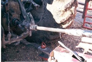 |
| Figure 1 – Unguarded PTO Shaft |
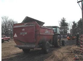
On November 11, 2002, a 45-year old male farm worker was killed when he became entangled in an unguarded rotating power take off (PTO) shaft at the tractor connection (See Figure 1). The mixer had undergone repair and its u-joint and PTO shaft were unguarded. The tractor PTO lever was located on the operator’s right side while seated in the tractor. The mixer had a moveable scale that was attached to a stationary arm that could be moved to face either side of the mixer. The victim loaded the mixer with supplements and then had driven the tractor/mixer to the bunker silo area to add haylage to the supplements. He drove the tractor into the bunker area from a north to south direction instead of his usual approach, which is in a south to north direction. He had dismounted from the tractor and left the tractor running; it is unknown if the PTO was engaged or disengaged when he dismounted. He was working alone and the event was unwitnessed. His left hand/arm became entangled in the rotating PTO. His clothing was ripped off and his left arm severed at the shoulder. Another employee found the victim with his head by the driver side rear tractor wheel and his feet facing the mixer. This employee turned off the tractor and contacted another employee for help. The second employee ran to assist the victim; when the second employee determined there was nothing he could do, he called the farm owner to obtain the exact farm location address and then called 911 with this information. Emergency response arrived and the victim was declared dead at the scene.
RECOMMENDATIONS
- All rotating shafts, including PTO drivelines, should be covered by shields/guards in good condition to prevent worker contact with rotating parts.
- Tractor operators should engage/disengage the PTO while seated in the tractor operator seat.
- Loose or frayed clothing that can get caught in machinery should not be worn.
- Employers should establish a safety plan that includes a farm emergency plan that identifies emergency responsibilities of individuals working on the farm, an emergency contact list, and farm location by the telephone.
INTRODUCTION
On Friday, November 1, 2002, a 45-year old male farm hand was killed when he became entangled in an unguarded powered take off (PTO) shaft. On Monday, November 4, 2002 MIFACE researchers were informed of the farm work-related fatality by the Michigan Occupational Safety and Health Act (MIOSHA) personnel who had received a report on their 24 hour-a-day hotline that a work-related fatal injury had occurred on November 1, 2002. On March 20, 2003, MIFACE researchers interviewed the farm owner and viewed the tractor involved in the incident, which was in a local equipment repair shop. The MIFACE researchers also visited the feedlot where the incident took place and viewed the feed mixer. During the course of writing this report, the medical examiners report, death certificate, sheriff department report and several pictures taken at the incident site. The operator’s manual and parts book for the feed mixer was obtained from the farm owner. MIFACE also obtained the MIOSHA citations issued to the farm.
The MIOSHA investigation resulted in two citations being issued to the company: one citation for failing to install a master shield or other protective guarding on all power take-off shafts and one for failing to notify MIOSHA of the fatality within 8 hours of the fatality.
The dairy farm where the deceased worked has over 160 head of dairy cows. The farm has 5 full time and 2 part-time employees. They also grow their own feed. The corn and haylage are stored in bunker silos. There was no written health and safety plan, although equipment manuals were available for equipment used on the farm. MIFACE pictures of the Oliver tractor were taken at the repair shop. The pictures of the mixer were taken at the site of the incident. The pictures taken at the incident site are a re-enactment of the scene of the accident; the tractor towing the mixer was not the tractor involved in the incident. Figure 1, Figure 4 and Figure 8 are photographs taken at the scene by the responding sheriff department.
INVESTIGATION
The victim had worked at the farm for 28 years, and was currently assigned to feeding the dairy cows. He was an hourly, full time employee who worked 10-hour days on the farm. He arrived at work at approximately 6:00am on the day of the incident. He was very familiar with the work being performed – he performed the job on a daily basis. His job was feeding the dairy herd. The herd was divided into feeding and milking groups. The feed mixer was loaded the night before for feeding the first group of cows. The victim would arrive at the farm and distribute this feed to the first group of cows. He would then load the mixer for each subsequent group of cows. According to the farm owner, the victim had been sick, and had returned from being out sick 2 days before. The farm owner said that the victim was pale and still not feeling well the days he was back at work and that he had flu-like symptoms. The victim was dressed in “well-worn” overalls and jacket, with threads and pieces of material torn off/hanging from his clothing. The victim was right handed and approximately 5’8″ tall.
The victim used a 1950 Oliver tractor, which was purchased used, to tow the feed mixer. The PTO lever was located on the back of the tractor frame on the operator’s right hand side. The PTO required some effort to engage/disengage; the farm owner indicated scratches on the tractor frame that were a result of where the lever had rubbed against the tractor frame. The tractor was still in the repair shop when the MIFACE researchers visited the farm location. The PTO lever was approximately 5’4″ from the ground. The center of the PTO to the PTO lever was approximately 21″. The farm owner stated that the PTO lever “pushed forward hard”.
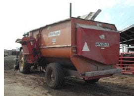
The Knight brand of Auger-Mixer wagon used by the farm operation was a Reel Auggie 3450 tow type feed mixer. It was purchased new in 1996 and was used to mix feed for the dairy cows (See Figure 2). All safety decals were present and readable on the mixer. The mixer had 2 hatches that could be opened to load the mixer from the top with feed. The top of the mixer on the auger side (low side) was 7’3″. The top of the mixer reel side (high side) 8’6″. The mixer is equipped with a scale mounted on a stationary arm. The scale is capable of pivoting side-to-side to measure feed weights (See Figure 3). The scale is approximately 6 feet off of the ground. The operator’s manual stated that when loading hay, it is helpful to have the PTO engaged and the mixer knives running during the loading procedure when hay is added to the mixer. The manual also recommends that the hay be loaded on the auger side (the low side of the mixer) to facilitate mixing of the hay. When loading hay, the manual also recommends that the mixer should be running at least at 2/3 to 3/4 rated speed.
 |
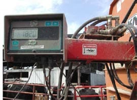 |
| Figure 2 – Knight Brand of Auger-Mixer Wagon | Figure 3 – Mixer Scale |
The normal mixer loading procedure was to first add feed supplements at another location on the farm site. To add the feed supplements, the mixer is backed up to the unloading chute at the supplement building with the auger side next to the building. The scale is directed to the auger side (the scale face is in the same direction as the low side of the mixer and faces the supplement building) to determine the supplement weight entering the mixer. After loading the supplements, the tractor and mixer is driven to the bunker silo area on the farm, to continue loading the mixer. Traveling from the supplement location, the tractor would normally enter the bunker silo area from the south; the tractor/mixer faces north. Positioning the tractor/mixer so it faces north places the reel side (high side) of the mixer toward the feeding/milking area and the auger side (low side) of the mixer (with visible scale face) toward the bunkers to allow for easier loading of corn/hay into the auger side of the mixer. The tractor would also be oriented so the operator, if standing on the ground, would not have to reach across the PTO drive shaft to “push” the PTO lever forward to engage the PTO. As told to the MIFACE researchers, the owner said that the operator, if necessary, while standing on the ground would reach around the tractor fender to engage the PTO.
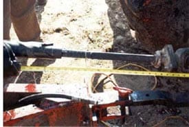
The farm owner indicated that the mixer had previously failed due to a “bad” universal joint of the PTO driveline shaft. The mixer was sent out to a farm equipment repair shop to be fixed. When the mixer was returned, it did not have a PTO shield. Several days later, the farm owner obtained a shield, and instructed the victim to place the shield on the PTO. The victim did not place the shield on the PTO – he replaced the PTO shaft with an alternate shaft that did not have PTO shielding. The police report of this incident indicated that the alternate PTO shaft was 50 inches in total length. The PTO drive shaft closest to the tractor to 20 inches back to the feed mixer was not shielded (See Figure 4 ). The mixer’s universal joint that connected to the drive shaft housing was also not covered with a protective housing.
 |
 |
| Figure 4 – Unguarded PTO Shaft | Figure 5 – Tractor/mixer facing south instead of north |
On the day of the incident, the victim drove the tractor so it entered the bunker area from the north instead of his usual approach, which is from the south. The farm owner stated that other employees said that they had seen the victim enter the bunker area from the north prior to this incident as a “change of pace”. This positioning of the tractor/mixer had several work practice implications: (1) the auger side of the mixer and the scale face were directed to the feeding/milking area rather than facing the bunker silos, (2) the scale face would need repositioning in order to be seen from the bunker silo side, (3) if standing on the ground, access to the PTO lever was by reaching across the unguarded PTO shaft instead of around the tractor bumper. (See Figure 5 for a re-enactment of the position of the mixer/tractor). Pictures taken at the incident site by the sheriff department showed the hatch open as reenacted in Figure 5 . Sheriff photographs taken at the time of the incident showed that the mixer was very close to the milking/feed lot fencing and that it would be difficult to load the feed with the tractor loader on the auger side. It is unknown if the victim was attempting to load the mixer from the reel side facing the bunker or the auger side facing the milking/feed lot. The pictures also showed two pitchforks leaning against the fencing. It is unknown if these pitchforks were being used by the victim.
 |
| Figure 6 – Reaching for PTO lever |
It is unknown if the victim disengaged the PTO when he dismounted the tractor. Another employee saw the victim pull into the feed bunker area. While herding cows into the milking parlor, this employee heard the tractor “rev up”. He looked over and saw the victim lying on the ground. The mixer auger was operating. The victim’s left arm was severed below the shoulder and his clothes were ripped off. He also noted that the tractor equipped with the front-end loader used to load silage into the mixer was not running. The employee contacted another employee who tried to assist the victim, but could not. The victim’s head was lying inside the driver’s side rear wheel with his feet directed toward the mixer. This employee called the farm owner for the correct address of the farm and then called for emergency response. Emergency response arrived, and the victim was declared dead at the scene.
The event was unwitnessed; possible scenarios that have been developed are:
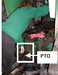
- The victim did not engage the PTO prior to dismounting from the tractor. While standing on the ground, he reached across the unguarded PTO and attempted to engage the PTO with his right hand. A possible position of the victim is illustrated in Figure 6. To push the PTO lever forward from this position may have caused him to be off-balance once the PTO engaged. After engaging the PTO, he may have lost his balance and while trying to recover, his hand and/or a piece of his clothing became caught in the unguarded, rotating PTO. A similar scenario is that he successfully activated the PTO and while moving away, the position of his left arm and/or piece of clothing may have been near the PTO and became entangled in the unguarded shaft. Figure 6 shows the protective shield on the tractor, behind the PTO lever that was installed at the repair shop. At the time of the incident, the shield was not present.
Figure 7 – Scale moved into position 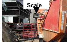
Figure 7 – Scale moved into position The victim left the tractor running and the PTO engaged. Because the scale was facing the feedlot instead of the bunker silos, he needed to pivot the face of the scale so he could see it while loading. He may have leaned forward slightly to take hold of the scale, in doing so; his sleeve and/or other piece of clothing became entangled in the unguarded PTO shaft. See Figure 7. Figure 7 shows the mixer PTO shield in place; it was not present at the time of the incident.
- It could be a combination of each of these scenarios – he may have had to activate the PTO and moving over to the scale, his hand/clothing became entangled in the PTO.
CAUSE OF DEATH
The cause of death as stated on the death certificate was multiple trauma. The results of all toxicological tests were negative.
RECOMMENDATIONS/DISCUSSION
• All rotating shafts, including PTO drivelines, should be covered by shields/guards in good condition to prevent worker contact with rotating parts
It takes only about one second to completely strip off an article of clothing or if the cloth does not tear away, to wrap a body or body part around a shaft when a PTO shaft is operating at 540 rpm.
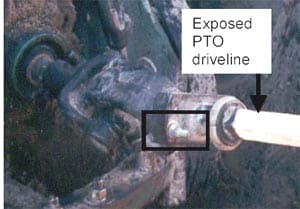 |
| Figure 8 – Exposed Bolts and driveline of PTO shaft |
A total shielding system for a PTO driveline includes a tractor master shield, the PTO driveline shield and an implement shield. Exposed rotating shafts are hazardous situations that can cause serious injury or death to workers. Properly designed guards and/or shields should cover any rotating shafts that a worker may be exposed to. In this incident, the PTO shaft was unguarded from the point where it was connected to the tractor to the mid-point of the shaft. As a result, one half of the rotating horizontal shaft between the tractor and the mixer was exposed (See Figure 8 ).
It is not known exactly how the victim became caught in the PTO shaft. The master shield should be kept in place at all times. A master shield should be removed only when required for hooking up special equipment with equivalent shielding. The PTO tractor stub shaft guard should be placed back on the tractor whenever PTO driven equipment is not being used. A guard covering the PTO may have prevented the victim from becoming entangled in the moving shaft.
• Tractor operators should engage/disengage the PTO while seated in the tractor operator seat.
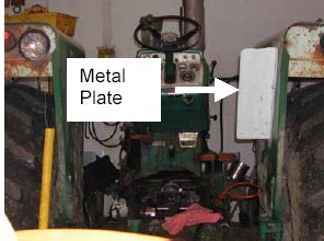 |
| Figure 9 – Metal Plate installed at repair shop |
In this incident, the operator manual for the mixer recommends that the mixer be in operation while loading haylage. It is recommended that if a tractor operator must make any operational maintenance inspection or repair to an implement or needs to go near a rotating PTO shaft, an operator should disengage the PTO shaft from the operator’s seat in the tractor, not reaching around the wheel fender. When the operator needed to turn the scale around so he could view it while loading haylage, he should have mounted the tractor, disengaged the PTO from the operator’s seat, dismounted, moved the scale, then climbed back into the operator’s seat to engage the PTO again. A safety “good rule of thumb” is to stay at least your height away from a rotating driveline.
Note: since the accident, while the tractor was in the repair shop, the farm owner installed a metal plate so that the PTO lever could not be engaged from ground level, only from the tractor operator’s seat. See Figure 9.
• Loose or frayed clothing that can get caught in machinery should not be worn.
The risk of entanglement in rotating shafts and machine components can be reduced if operators do not wear loose fitting clothing. Work clothing should be well-fitting and zippered or buttoned, not open. Frayed or loose fitting clothes, jackets and sweatshirts with drawstrings, and boots or shoes with long shoelaces should be avoided. Long hair should be tied back or under a cap.
• Employers should establish a safety plan that includes a farm emergency plan that identifies emergency responsibilities of individuals working on the farm, an emergency contact list, and farm location by the telephone.
There are no legal requirements in Michigan for a written safety plan in agricultural industries. We recommend a written safety plan. This plan will identify the safety and health hazards for the farm, so hazard controls can be developed. A safety plan, that is communicated to all who work on the farm will help raise awareness of safety issues, promote safe work practices, and have additional benefits of increasing work efficiency, and minimizing costs (a written safety plan may reduce worker compensation premiums). A safety plan should include work rules as well as emergency procedures.
The Farm Emergency Plan Workbook assembled by the Ontario Ministry of Agriculture and Food can be used as a template for a farm emergency plan. The workbook includes gathering background information about the farm; a farm family emergency plan and an emergency plan for your farm operations. This workbook can be downloaded from the Internet: www.gov.on.ca/omafra/english/research/risk/pdfs/fepwbook.pdf. (Link no longer valid, 9/13/2005)
Another resource for an emergency action plan is an MSU Extension Bulletin E-2575, Emergency Planning for the Farm. This bulletin includes SARA Title III Emergency Planning Requirements. This bulletin can be downloaded from the Internet: http://web2.msue.msu.edu/bulletins2/product/emergency-planning-for-the-farm-downloadable-pdf-1093.cfmexternal icon (Link updated 3/27/2013).
Copies of the Farm Emergency Plan Workbook and Emergency Planning for the Farm are included with this report.
REFERENCES
National Safety Council Fact Sheet Library, PTO Safety, Internet Resource: www.nsc.org/news_resources/resources/documents/power_Take_off%20(PTO).pdfpdf iconexternal icon (Link updated 3/25/2013)
Agricultural Implement Drivelines, Safety Manual for owners and operators, Agricultural Driveline Manufacturers Association, copyright 1997.
Operator’s Manual and Parts Book, Knight Manufacturing Corp., 1501 West 7th Avenue, P.O. Box 167, Brodhead, WI 53520-0167
Accident Compensation Corporation Internet website, Injury Prevention, Rural Safety, Emergency plan. www.acc.org.nz/injury-prevention/ruralsafe/is-your-farm-safe/emergency-plan (Link no longer valid, 9/13/2005)
Farm Emergency Plan Workbook, Ontario Ministry of Agriculture and Food www.gov.on.ca/omafra/english/research/risk/pdfs/fepwbook.pdf (Link no longer valid, 9/13/2005)
Emergency Planning for the Farm, Michigan State University Extension Bulletin E-2575, Internet website location http://web2.msue.msu.edu/bulletins2/product/emergency-planning-for-the-farm-downloadable-pdf-1093.cfmexternal icon (Link updated 3/27/2013)
MIFACE (Michigan Fatality and Control Evaluation), Michigan State University (MSU) Occupational & Environmental Medicine, 117 West Fee Hall, East Lansing, Michigan 48824-1315. This information is for educational purposes only. This MIFACE report becomes public property upon publication and may be printed verbatim with credit to MSU. Reprinting cannot be used to endorse or advertise a commercial product or company. All rights reserved. MSU is an affirmative-action, equal opportunity employer. 6/2/03